
Horizontal tension tester's fixture for round wire concentric-lay-stranded overhead conductors

A horizontal tensile test, overhead wire technology, applied in measuring devices, instruments, scientific instruments, etc., can solve the problems of heavy weight, complex chuck structure, influence, etc., to increase the contact area, reduce broken strands or broken wires the effect of the probability of

Inactive Publication Date: 2015-12-23
STATE GRID CORP OF CHINA +1
View PDF9 Cites 3 Cited by
  • Summary
  • Abstract
  • Description
  • Claims
  • Application Information

AI Technical Summary

Problems solved by technology

When the stress-strain curve test is performed on the wire, both ends of the sample need to be clamped. The wire clamping methods include casting method, sleeve pressure method, winding method and direct clamping method. The direct clamping method has the characteristics of easy operation. However, the traditional chuck is generally complex in structure and heavy in weight. When used on a horizontal tensile testing machine, its own gravity has a certain degree of influence on the test results.

Method used


Image

  • Horizontal tension tester's fixture for round wire concentric-lay-stranded overhead conductors
  • Horizontal tension tester's fixture for round wire concentric-lay-stranded overhead conductors
  • Horizontal tension tester's fixture for round wire concentric-lay-stranded overhead conductors

Examples


Embodiment 1

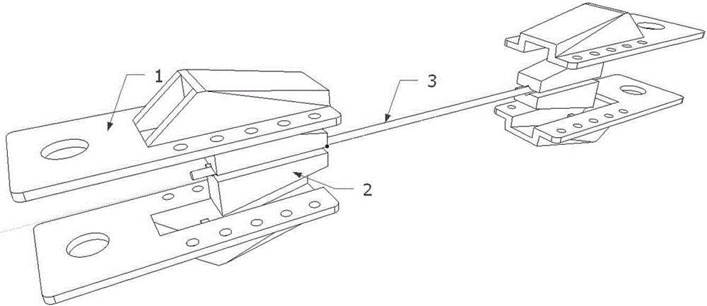
[0021] see figure 1 , a round wire concentric stranded overhead wire clamp used for a horizontal tensile testing machine includes a pair of clamping mechanisms with the same specifications, and each pair of clamping mechanisms includes a pair of clamping blocks and a pair of clamp shells.

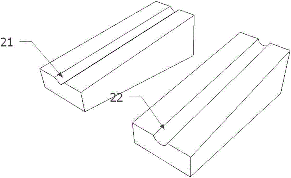
[0022] see image 3 , a pair of clamping blocks are composed of clamping blocks 2 corresponding to the two clamping jaws. The two clamping blocks are respectively provided with groove-shaped jaws 21 for clamping round concentric twisted overhead wires. The jaws 21 are V-shaped jaws; the clamping block 2 is a right-angled trapezoidal block, and the jaws 21 are located on one side of the clamping block 2 at a right angle, and are in a through shape. Two clamping blocks 2 cooperate to form an isosceles trapezoidal block. The jaw ends of a pair of clamping blocks are clamping ends, and the corresponding other ends are positioning ends.

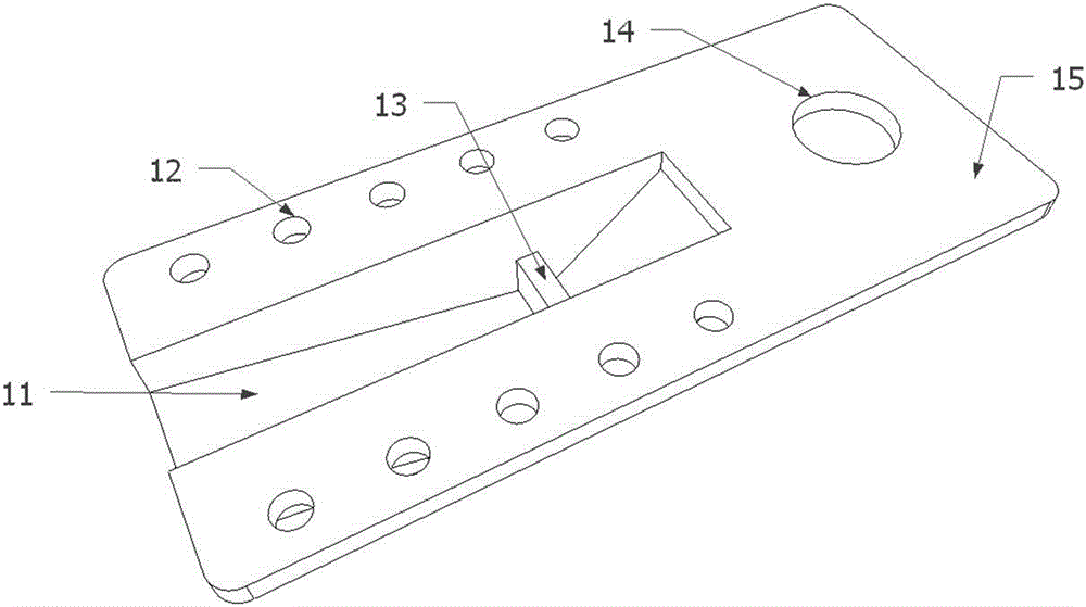
[0023] see figure 2 , a pair of clamp shells are comp...

Embodiment 2

[0028] When testing aluminum stranded aerial conductors, steel-cored aluminum stranded overhead conductors, or other combined aluminum and steel conductors, it is necessary to wrap aluminum foil or aluminum strips at both ends of the overhead conductors first, and select a clamp with an arc-shaped jaw 22 of corresponding specifications. block, see image 3 . Other steps are with embodiment 1.


PUM


Abstract

The invention relates to a horizontal tension tester's fixture for round wire concentric-lay-stranded overhead conductors. The fixture of the invention comprises a pair of clamping mechanisms with consistent specification. Each clamping mechanism comprises a pair of fixture blocks and a pair of fixture shells. The pair of fixture blocks is formed by cooperation of two clamping blocks with their jaws being corresponding to each other. The two clamping blocks are respectively provided with groove-like jaws used for clamping a round wire concentric-lay-stranded overhead conductor. The jaw end of the pair of fixture blocks is a clamping end, and the other corresponding end is a positioning end. The pair of fixture shells is composed of two correspondingly-matched fixed bodies which are respectively equipped with fixture block grooves. The pair of fixture blocks is correspondingly positioned inside the fixture block grooves of the pair of fixture shells, and the clamping end of the pair of fixture blocks is positioned outside the pair of fixture shells. The pair of fixture shells on the periphery of the fixture block grooves is fixedly connected through threaded connectors. When the fixture is in use, the pair of clamping mechanisms respectively clamps two ends of the overhead conductor and realizes self-locking when stressing. By replacing different sizes of the fixture blocks, the fixture is suitable for overhead conductors with different sectional areas.

Description

technical field [0001] The invention belongs to the technical field of stress-strain detection of round wire concentric stranded overhead wires, and in particular relates to a clamp for round wire concentric stranded overhead wires suitable for a horizontal tensile testing machine. [0002] By changing the size of the jaws, it can be applied to round wire concentric twisted overhead conductors with different cross-sectional areas, which is simple and efficient. Background technique [0003] Round wire concentric stranded overhead wire refers to a wire twisted with one or more layers of single wires spirally twisted around one or a bunch of central wire cores, and the adjacent layers are twisted in opposite directions. The round wire concentric stranded overhead conductor needs to be laid overhead, so the conductor itself will bear a certain tension. If the rated tensile strength of the overhead conductor is unqualified, it is easy to cause a disconnection accident. In addit...

Claims


Application Information

Patent Timeline
Patent Type & Authority Applications(China)
IPC IPC(8): G01N3/04
Inventor 缪春辉陈国宏王若民张海
Owner STATE GRID CORP OF CHINA
Learn More