
Dynamic simulation test method for small power compressor motor stator iron core verticality

A dynamic simulation, motor stator technology, applied in the direction of measuring devices, instruments, etc., can solve the problems affecting the performance of the motor, the working performance of the stator, the deviation of the concentricity of the center hole of the stator, etc., and achieve the effect of easy operation and work efficiency.

Active Publication Date: 2015-12-23
浙江迪贝电气股份有限公司
View PDF8 Cites 0 Cited by
  • Summary
  • Abstract
  • Description
  • Claims
  • Application Information

AI Technical Summary

Problems solved by technology

[0003] If the stator that has not passed the verticality test is directly installed on the cylinder block of the compressor, there may be a problem of deviation of the concentricity of the stator center hole, which will cause the rotor to generate rotation resistance. When the allowable deviation range is exceeded, the stator center hole wall and The outer wall of the rotor will generate frictional noise, which will inevitably directly affect the working performance of the stator, and ultimately affect the performance of the motor. Therefore, before the formed stator is delivered for installation, a practical method for testing the verticality of the formed stator is required.
[0004] At present, there is only a static test method for the verticality of the formed stator core. It needs tools such as feeler gauges to detect the gap between the static stator core and the static dummy shaft. The dynamic simulation test method for the verticality of the stator core of the small-power compressor motor is carried out under the background of this case.

Method used


Image

  • Dynamic simulation test method for small power compressor motor stator iron core verticality
  • Dynamic simulation test method for small power compressor motor stator iron core verticality
  • Dynamic simulation test method for small power compressor motor stator iron core verticality

Examples


Embodiment Construction

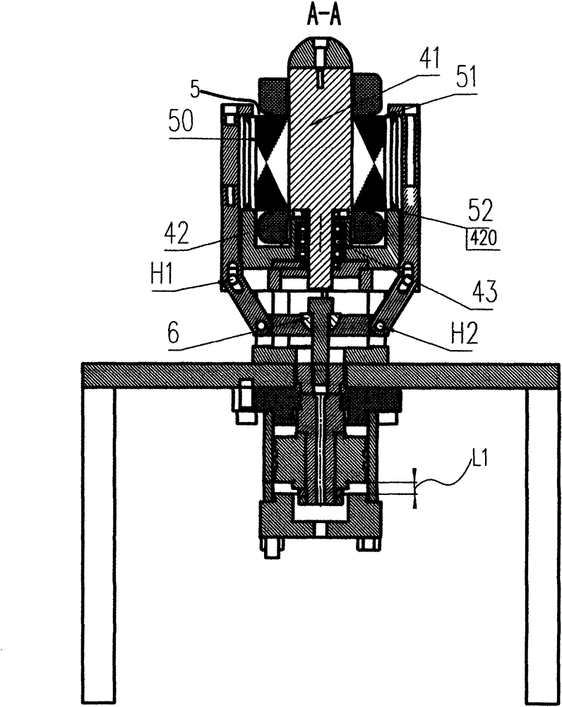
[0029] see figure 1 , 2 , Shown in 3 is a preferred embodiment of the present invention.

[0030] A dynamic simulation test method for the verticality of the stator core of a small-power compressor motor, the method includes the following steps in sequence:

[0031] a) Before implementing the dynamic simulation test, the formed stator (not shown) is locked to the installation plane of the compressor cylinder block (not shown), and the torque during locking is measured as 15~ 22N.m, wherein, the central hole diameter of the stator core of the formed stator is Dmm, and the diameter of the rotor (not shown) matched with the formed stator is [D-(0.8~1.0)]mm.

[0032] The stack height of the stator core of the formed stator ranges from 60mm to 108mm.

[0033] In the formed stator in this embodiment, the central aperture of the stator core is 79.3 mm, the stack height of the stator core is 108 mm, the diameter of the matching rotor is 78.4 mm, and the torque when fastened with bo...


PUM


Abstract

The invention discloses a dynamic simulation test method for small power compressor motor stator iron core verticality. The method comprises steps: a) a forming stator is locked on a mounting plane of a cylinder seat at 15 to 22N.m before the test, the central aperture of the stator iron core is set to be Dmm, and the rotor diameter is 0.8 to 1.0mm smaller than the aperture; b) the test is carried out on a special simulation tester, four clamping claws are opened, a to-be-tested stator is sleeved on a simulation rotor, the bottom end surface of the stator iron core touches the horizontal top surface of a mold seat, the central aperture of the stator iron core is also Dmm, and the diameter of the simulation rotor is 0.3 to 0.4mm smaller than the aperture; c) the clamping claws are closed, and the stator iron core top end surface is touched; d) a hydraulic adjustable tension mechanism is opened, a piston, a tension connection rod and a pulling plate are pushed to move downwardly until the clamping claws uniformly apply a 15 to 22N.m pre-tightening force on the stator iron core when the piston moves for 15 to 23mm; and e) the simulation rotor is rotated to test the dynamic air gap between the to-be-tested stator and the simulation rotor. The method of the invention realizes the test is carried out when the stator is pre-tightened and the simulation rotor tries to rotate, and the work efficiency is high.

Description

【Technical field】 [0001] The invention relates to a test method for the verticality of the stator iron core of a motor, in particular to a dynamic simulation test method for the verticality of the stator core of a small-power compressor motor. 【Background technique】 [0002] The motor is a high-speed rotating part that converts electrical energy into mechanical energy. It includes a stator and a rotatable rotor. The existing stator core is usually made of multiple pieces of silicon steel sheets riveted into a whole body. Before the torque is locked to the installation plane of the compressor cylinder block, the verticality test process is still required. The vertical accuracy of the stator core can effectively improve the overall performance and pass rate of the motor. [0003] If the stator that has not passed the verticality test is directly installed on the cylinder block of the compressor, there may be a problem of deviation of the concentricity of the stator center hole...

Claims


Application Information

Patent Timeline
IPC IPC(8): G01B21/22
Inventor 王江波王建鸿马树江吴储正张文波
Owner 浙江迪贝电气股份有限公司
Learn More