
Compact type redundant sealing structure

A sealing structure, compact technology, applied in the direction of engine sealing, engine components, mechanical equipment, etc., can solve the problems that the sealing redundant design method cannot be implemented, it is difficult to obtain a satisfactory sealing effect, and the sealing redundant design is difficult, so as to avoid Oil leakage phenomenon, compact structure, simple structure effect

Active Publication Date: 2015-12-23
BEIJING RES INST OF PRECISE MECHATRONICS CONTROLS +1
View PDF7 Cites 4 Cited by
  • Summary
  • Abstract
  • Description
  • Claims
  • Application Information

AI Technical Summary

Problems solved by technology

Due to the limitation of structural space, if the structure of the sealing part is compact, the implementation of the above-mentioned second sealing structure may lead to structural interference, making the above-mentioned sealing redundant design method impossible to implement
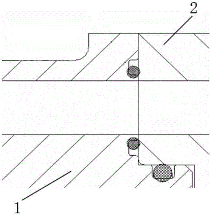
The sealing of the oil hole between the shells of the electro-hydraulic servo mechanism is limited by the structural space, and the redundant design of the seal is relatively difficult. See figure 1 , the oil hole between the first housing and the second housing is sealed with an axial sealing structure. If two sealing structures of the same type are used for redundant sealing, an additional seal is added on the radially outer side of the first seal. If the sealing structure is used, the second sealing structure interferes with the spigot below the oil hole of the first housing, and there is no room for implementation. It is difficult to obtain a satisfactory sealing effect with a single sealing structure, and oil leakage often occurs

Method used


Image

  • Compact type redundant sealing structure
  • Compact type redundant sealing structure
  • Compact type redundant sealing structure

Examples


Embodiment Construction

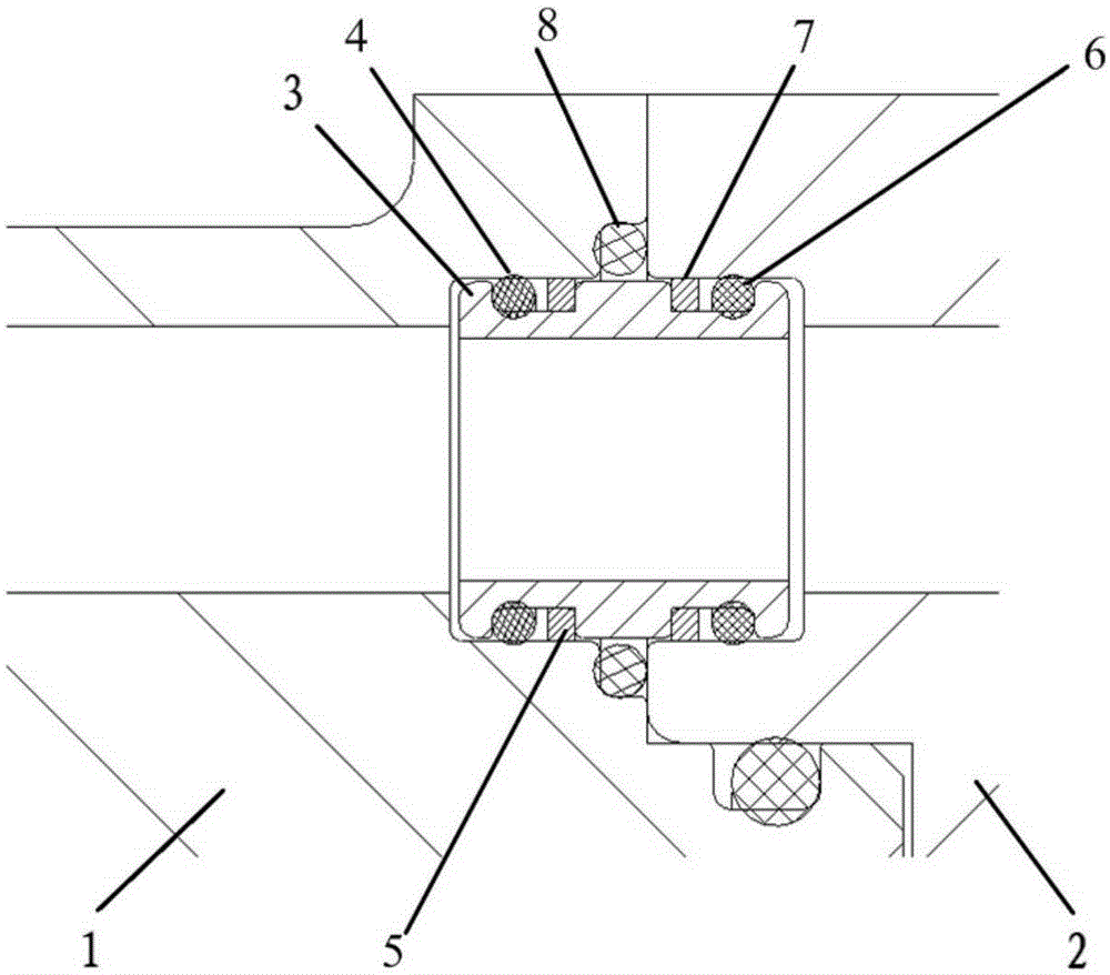
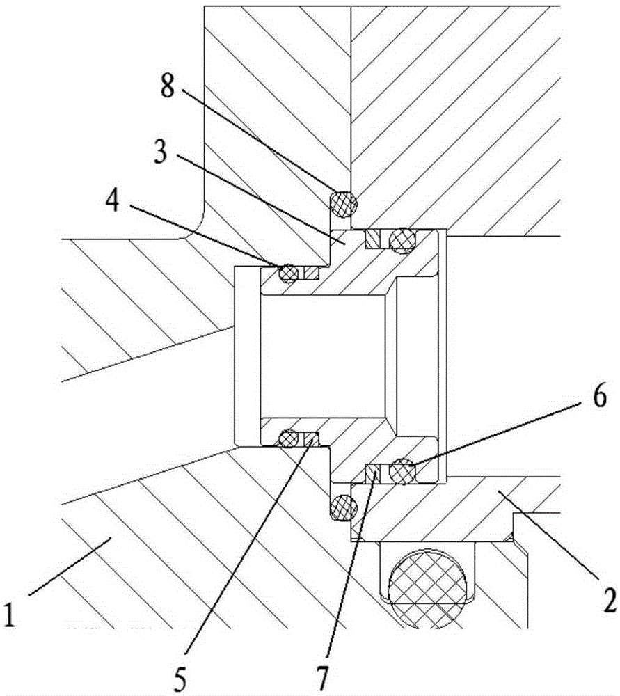
[0016] Such as figure 2 As shown, the first embodiment of the present invention includes a first housing 1, a second housing 2, an oil passing pin 3, a first sealing ring 4, a second sealing ring 6, a third sealing ring 8, a first Retaining ring 5 and second retaining ring 7.

[0017] The first housing 1 and the second housing 2 have oil through holes. In order to achieve redundant sealing, one end of the first housing 1 and the second housing 2 are respectively provided with an axial angle connected to the oil through holes. The first annular groove and the second annular groove, an oil-passing pin 3 is installed between the oil-passing holes of the first housing 1 and the second housing 2, and the two ends of the oil-passing pin 3 are connected to the first annular groove and the second annular groove respectively. The grooves are matched, there is a through hole in the oil through pin 3; the two ends of the through hole of the oil through pin 3 are as consistent as possible w...


PUM


Abstract

A compact type redundant sealing structure is characterized by comprising a first shell (1), a second shell (2), an oil introducing pin (3), a first sealing ring (4), a second sealing ring (6) and a third sealing ring (8); the oil introducing pin (3) is arranged at the joint between the first shell (1) and the second shell (2); the side faces of the two ends of the oil introducing pin (3) are provided with a first sealing ring groove and a second sealing ring groove respectively; the first sealing ring (4) and the second sealing ring (6) are arranged in the first sealing ring groove and the second sealing ring groove respectively; the first shell (1) or the second shell (2) is further provided with a third sealing ring groove or an annular hole; the third sealing ring (8) is arranged in the third sealing ring groove or the annular hole; the third sealing ring (8) and the first sealing ring (4) form a redundant sealing structure on one side; and the third sealing ring (8) and the second sealing ring (6) form a redundant sealing structure on the other side. The compact type redundant sealing structure is compact in structure, good in reliability, and capable of achieving dual seal of the compact-structure portion and effectively preventing oil leakage which frequently appears on a single-seal structure.

Description

Technical field [0001] The invention belongs to a sealing structure, particularly a redundant sealing structure. Background technique [0002] Sealing performance is one of the key performances of the electro-hydraulic servo mechanism. The performance of the servo machine is reduced due to seal failure or the failure accounts for 50% of the servo failures. Therefore, the reliability of the seal is particularly important for the electro-hydraulic servo mechanism. Single-channel sealing structure, under the comprehensive influence of the consistency of seal performance, structural parts processing, assembly errors, and external environment, oil leakage and failure often occur. Carry out seal redundancy design for important sealing parts, that is, set two sealing structures at the sealing parts, and the second seal is used as a redundant structure. When the first sealing structure fails, the second sealing structure can still have a sealing effect. Effectively improve product seali...

Claims


Application Information

Patent Timeline
Patent Type & Authority Applications(China)
IPC IPC(8): F16J15/06
Inventor 刘洪赵迎鑫陈克勤姜庆义付宁
Owner BEIJING RES INST OF PRECISE MECHATRONICS CONTROLS
Learn More