Welding machine

A welding ring machine and welding ring technology, applied in welding equipment, auxiliary welding equipment, welding/cutting auxiliary equipment, etc., can solve the problems of damage to the eyes of the operator, poor welding quality consistency, burn through the operator, etc., to prevent Danger, ensure the consistency of welding quality, and ensure the effect of personal safety

Active Publication Date: 2017-02-01
DONGGUAN SANNIAN INTELLIGENT TECH CO LTD
View PDF6 Cites 0 Cited by
  • Summary
  • Abstract
  • Description
  • Claims
  • Application Information

AI Technical Summary

Problems solved by technology

[0004] However, because the welding ring device is operated by the operator on-site and purely by hand, the burden on the operator is increased; at the same time, a large amount of welding spatter and strong light will be produced during the welding of the two welding ends of the metal ring. This strong light seriously damages the eyes of the operator, and the welding spatter has the defects of hurting the operator and burning through the clothes of the operator due to the extremely high temperature, thus bringing harm to the personal safety of the operator; moreover , since the welding quality of the two welding ends of the metal ring is determined by the experience of the operator, which is highly subjective, the consistency of the welding quality of the two welding ends of the metal ring is poor

Method used


Image

  • Welding machine
  • Welding machine
  • Welding machine

Examples


Embodiment Construction

[0024] In order to describe the technical content and structural features of the present invention in detail, further descriptions will be made below in conjunction with the embodiments and accompanying drawings.

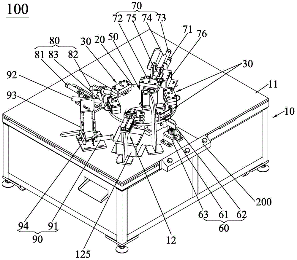
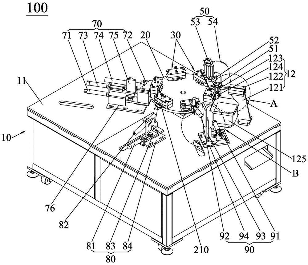
[0025] see figure 1 and figure 2 , the coil welding machine 100 of the present invention is suitable for electrical connection with a controller 200, and the coil welding machine 100 is controlled by the controller 200 to further improve the degree of automation of the coil welding machine 100 of the present invention, and the controller 200 The structure of is well known to those of ordinary skill in the art, so its structure will not be described in detail here.

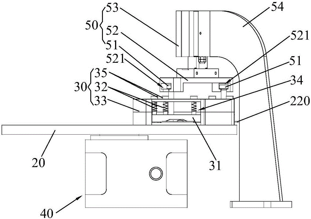
[0026] And the welding ring machine 100 of the present invention is used for welding the two welding ends of the metal ring 210 together, so that the two welding ends of the metal ring 210 that are separated from each other are welded together to form a Figure 5 The solder diagram 220 is shown. Wher...


PUM


Abstract

The invention discloses a ring welding machine. The ring welding machine comprises a machine frame, a rotary table, pressing fixtures arranged in the circumferential direction of the rotary table, a rotary table driving mechanism, a lifting mechanism, a positioning mechanism, a first welding mechanism, a second welding mechanism and a third welding mechanism. The lifting mechanism, the positioning mechanism, the first welding mechanism, the second welding mechanism and the third welding mechanism are sequentially installed on the machine frame in the rotation direction of the rotary table. The rotary table drives the pressing fixtures to correspond to the lifting mechanism, the positioning mechanism, the first welding mechanism, the second welding mechanism and the third welding mechanism respectively. The lifting mechanism is used for lifting the corresponding pressing fixture so as to enable the pressing fixture to release a compressed metal ring. The positioning mechanism positions the metal ring on the corresponding lifted pressing fixture. The first welding mechanism carries out necking on the two welding ends of the corresponding positioned metal ring and welding on the first position. The second welding mechanism carries out welding of the second position on the two welding ends of the corresponding metal ring processed by the first welding mechanism. The third welding mechanism carries out welding of the third position on the two welding ends of the corresponding metal ring processed by the second welding mechanism to enable the metal ring to form a welding ring, and automatic welding of the metal ring is achieved.

Description

technical field [0001] The invention relates to the field of welding, in particular to a ring welding machine capable of automatically welding two welding ends of metal rings together. Background technique [0002] With the continuous development of the economy and the continuous progress of science and technology, it provides a strong economic and technical support for the development of the enterprise, and promotes the enterprise to move towards the direction of intelligence and high integration, and the welding ring device is the intelligence developed by the enterprise. One of the customized products. [0003] As we all know, the welding ring device is a device that welds the two welding ends of the metal ring together. The welding ring device is to weld the two welding ends of the fixed metal ring by the operator on site and purely manual operation, so as to make the metal The purpose of welding the two welding ends of the ring together to form a welding ring. [0004...

Claims


Application Information

Patent Timeline
Patent Type & Authority Patents(China)
IPC IPC(8): B23K37/00B23K37/04
CPCB23K37/00B23K37/04
Inventor 段李文
Owner DONGGUAN SANNIAN INTELLIGENT TECH CO LTD
Why Eureka
Try Eureka