Rotatable headrest connection structure

A technology of rotating connection and connecting structure, which is applied in the direction of stools, other seating furniture, household appliances, etc., can solve the problems of low pillow end, low pillow end, discomfort, etc., and achieve production cost saving and simple structure Effect

Inactive Publication Date: 2015-12-23
ZHEJIANG ANJI XIANGTAI FURNITURE
View PDF8 Cites 0 Cited by
  • Summary
  • Abstract
  • Description
  • Claims
  • Application Information

AI Technical Summary

Problems solved by technology

[0003] When the backrest is turned back and forth, the end of the backrest will be lowered when the backrest is lowered, and the occupants will be very uncomfortable when resting. The angle adjustment of the existing backrest cannot make the backrest rotate horizontally in an approximately parallel plane. To meet the low adjustment of the end of the pillow

Method used


Image

  • Rotatable headrest connection structure
  • Rotatable headrest connection structure
  • Rotatable headrest connection structure

Examples


Embodiment 1

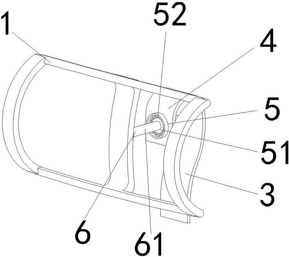
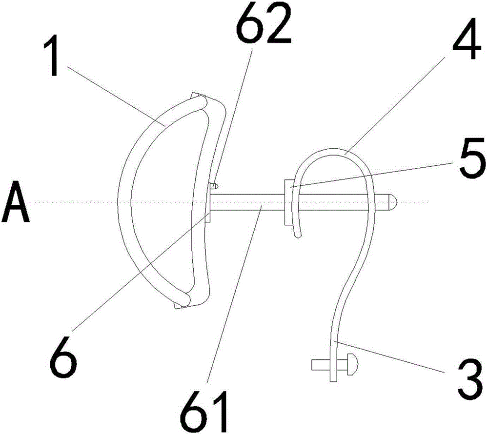
[0028] Embodiment one, such as figure 1 , figure 2 , image 3 and Figure 4 The shown a kind of headrest rotating connection structure comprises headrest supporting frame 1 and backrest supporting frame 2, and connecting structure body 3 is arranged between headrest supporting frame 1 and backrest supporting frame 2, and connecting structure body 3 includes can be connected by rivet. The connecting bracket 4 on the backrest support frame 2 is a cuboid block, and its upper part has a bend on the length side. The bending makes the side view of the connecting bracket 4 an inverted "U" shape, and one end of the bending The back support frame 2 is connected, and the other end is provided with a rotating receiving part 5 . One side of the "U"-shaped bending is provided with a rotating receiving part 5, and the other side is connected to the back support frame 2.

[0029] The rotation receiving part 5 includes a rotation limiting part 51 and a rotation positioning part 52. The r...

Embodiment 2

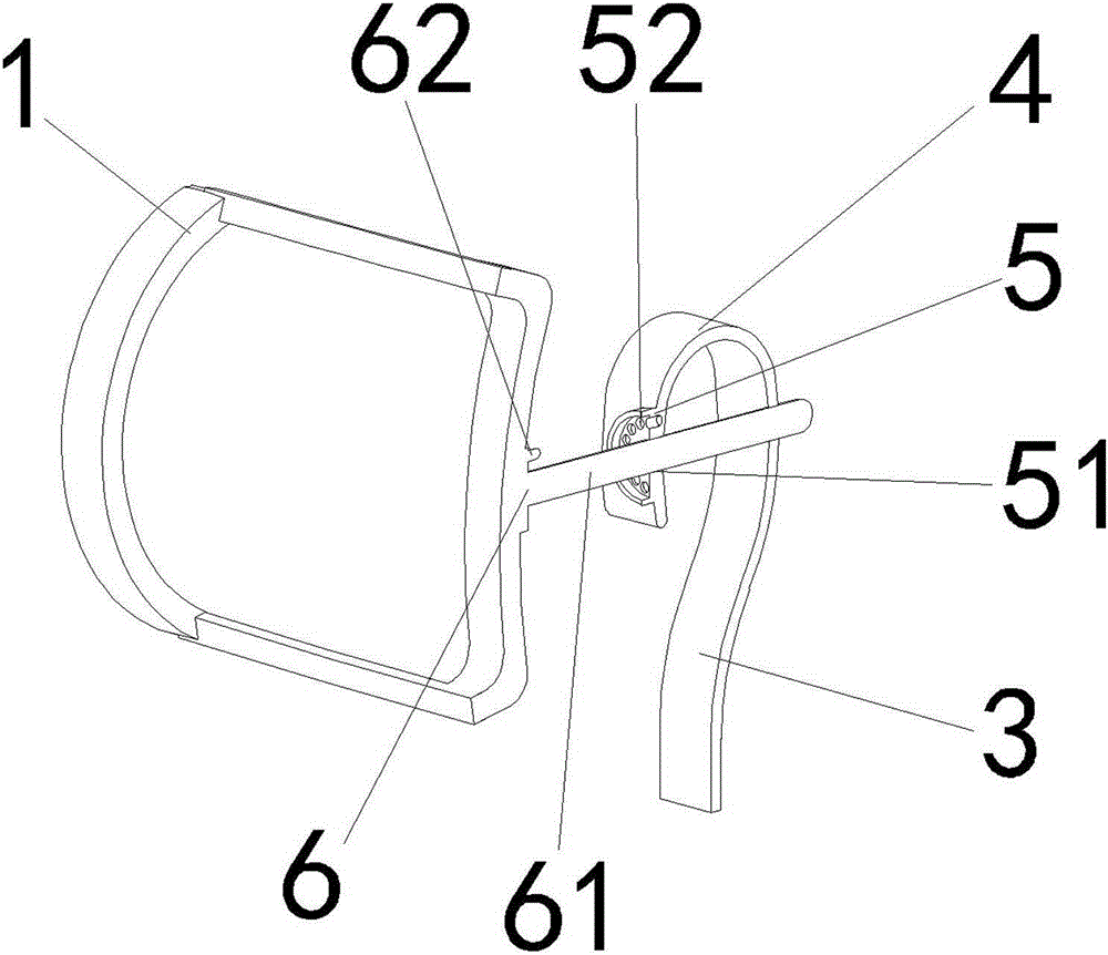
[0032] Embodiment two, such as Figure 5 , Image 6 and Figure 7 A headrest rotation connection structure shown includes a headrest support frame 1 and a backrest support frame 2, and a connection structure body 3 is arranged between the headrest support frame 1 and the backrest support frame 2, and the connection structure body 3 includes a body integrated with the backrest support frame 2. The formed connecting bracket 4 is provided with a rotating receiving part 5 on the connecting bracket 4. The rotating receiving part 5 includes a rotating limiting part 51 and a rotating positioning part 52. The rotating limiting part 51 is a rotating shaft fixing rod, and the rotating positioning part 52 is a A positioning groove arranged around the rotating shaft fixing rod.

[0033] A rotating part 6 is fixedly welded on the pillow support frame 1 , and the rotating part 6 includes a rotating shaft 61 and a positioning part 62 . Rotating shaft 61 comprises the axle sleeve that is f...


PUM


Abstract

The invention relates to a rotatable headrest connection structure, which belongs to the technical field of design, manufacturing and processing of lounge chair headrests. A connection structure body comprises a connecting bracket, a rotational connecting part and a rotatable part; the rotational connecting part and the rotatable part cooperatively shear a central rotational axis which is approximately perpendicular to the plane of a backrest-supporting frame and approximately parallel to the horizontal plane, and the rotatable part can be rotated by taking the central rotational axis as a rotational axis center, so that a headrest-supporting frame can be rotated within the plane of the headrest-supporting frame which is approximately parallel to the plane of the backrest-supporting frame. The adoption of the scheme achieves the purpose that when a backrest of a lounge chair is inclined backwardly to an approximately horizontal position, a headrest can be rotated within an approximately horizontal plane to adjust the low end of the headrest.

Description

technical field [0001] The invention belongs to the technical field of design, manufacture and processing of a pillow of a leisure chair, in particular to a rotating connection structure of a pillow. Background technique [0002] The headrest rotation direction of existing leisure chair is to turn to the back of the backrest from the front of the backrest; add. Because the upper end of the current headrest is generally slightly behind, and the lower end is generally slightly forward, the central axis of the headrest is basically parallel to the horizontal plane, and the head, neck and shoulders below the neck will not be adjusted by the offset of the headrest center axis. massage support. [0003] When the backrest is turned back and forth, the end of the backrest will be lowered when the backrest is lowered, and the occupants will be very uncomfortable when resting. The angle adjustment of the existing backrest cannot make the backrest rotate horizontally in an approximat...

Claims


Application Information

Patent Timeline
IPC IPC(8): A47C7/38
Inventor 杨余东
Owner ZHEJIANG ANJI XIANGTAI FURNITURE
Why Eureka
Try Eureka