Switch cabinet and control method thereof

A control method and technology of switchgear, applied in humidity control, non-electric variable control, control/regulation system, etc., can solve the problems of insufficient heating, excessive heating, affecting the service life, etc., to speed up dehumidification, ensure safety, and save money energy effect

Inactive Publication Date: 2015-12-16
安徽云控信息科技有限公司
View PDF4 Cites 8 Cited by
  • Summary
  • Abstract
  • Description
  • Claims
  • Application Information

AI Technical Summary

Problems solved by technology

In the prior art, the heating devices in the switchgear are mostly installed close to the installation structure of the electrical components. The electrical components are under the baking of the heating device for a long time, which will affect their service life, and the heating temperature cannot be controlled, which is prone to overheating or underheating. The problem is that when the heating is excessive, the electrical components will be seriously damaged, and the dehumidification effect will not be achieved if the heating is insufficient
In addition, the existing switch cabinets are generally not equipped with lighting equipment. When the power is cut off or repaired at night, the operation and maintenance personnel need to bring their own lighting equipment, which is very inconvenient

Method used


Image

  • Switch cabinet and control method thereof
  • Switch cabinet and control method thereof

Examples


Embodiment Construction

[0026] Below, the technical solution of the present invention will be described in detail through specific examples.

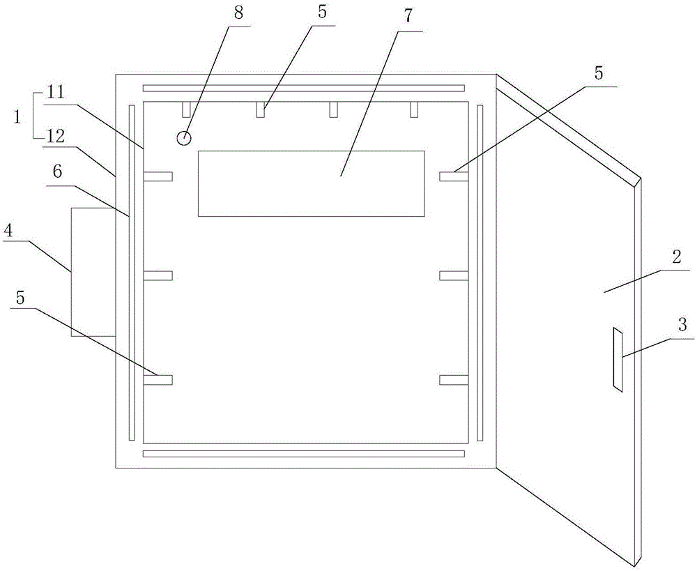
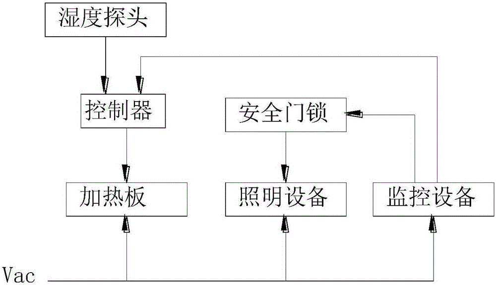
[0027] Such as Figure 1-2 as shown, figure 1 It is a structural schematic diagram of a switchgear proposed by the present invention; figure 2 It is a working principle diagram of a switchgear proposed by the present invention.

[0028] refer to Figure 1-2 , a switch cabinet proposed by the embodiment of the present invention, comprising: a humidity probe 8, a controller 4, a monitoring device, a cabinet body 1, a cabinet door 2 hinged to the cabinet body 1, and a safety door lock 3 installed in the cabinet door 2;

[0029] The humidity probe 8 is arranged in the cabinet 1 and the humidity probe 8 is connected to the controller 4 and feeds back the detection data to the controller 4. The controller 4 controls the on / off of the heating plate 6 through the data fed back by the humidity probe 8, thereby realizing heating. The purpose of control, to ensure t...


PUM


Abstract

The invention discloses a switch cabinet and a control method thereof. The switch cabinet comprises a humidity probe, a controller, monitoring equipment, a cabinet body, a cabinet door and a safety door lock, and is characterized in that the cabinet body comprises an inner shell and an outer shell, a gap is reserved between the outer wall of the inner shell and the inner wall of the outer shell so as to form a cavity, the wall surface of the inner shell is provided with air inlet holes, the inner side of the inner shell is provided with lighting equipment, and the lighting equipment is in linkage with the safety door lock; the safety door lock is connected with the monitoring equipment, and the on/off state of the safety door lock is monitored by the monitoring equipment; the monitoring equipment is connected with the controller so as to be used for transmitting a monitoring result to the controller; the outer shell is provided with an air-exchange hole, and the cavity is internally provided with a negative pressure generator at the part of the air-exchange hole; and the cavity is internally provided with a heating plate, the heating plate is connected with the controller, and on/off between the heating plate and a power supply is controlled by the controller. The switch cabinet disclosed by the invention realizes the purposes of controllable heating and being convenient for overhauling of the operation and maintenance personnel, and is energy-saving and safe.

Description

technical field [0001] The invention relates to the field of electrical equipment, in particular to a switch cabinet and a control method thereof. Background technique [0002] The switchgear is a commonly used electrical equipment, which mainly plays the role of opening and closing, controlling the transmission line, and protecting the electrical equipment. The working environment of the switchgear is different. Some switchgears work in an environment with high humidity. The moisture in the air can easily cause a short circuit of the electrical components in the switchgear. Therefore, a heating device needs to be added in the switchgear for dehumidification. In the prior art, the heating device in the switchgear is mostly installed close to the installation structure of the electrical components. The electrical components are under the baking of the heating device for a long time, which will affect their service life, and the heating temperature cannot be controlled, which ...

Claims


Application Information

Patent Timeline
Patent Type & Authority Applications(China)
IPC IPC(8): H02B1/28H02B1/24G05D22/02
Inventor 吴家猛吴刚陈铖
Owner 安徽云控信息科技有限公司
Why Eureka
Try Eureka