Underwater crack corrosion jet nozzle

A technology of jet nozzles and jets, applied in the direction of injection devices, injection devices, liquid injection devices, etc., can solve the problems of limiting cavitation jet erosion ability and prolonging the action time

Active Publication Date: 2015-12-16
ZHEJIANG UNIV
View PDF6 Cites 8 Cited by
  • Summary
  • Abstract
  • Description
  • Claims
  • Application Information

AI Technical Summary

Problems solved by technology

[0003] Traditional cavitation nozzles are divided into wake cavitation type, shear type and self-excited oscillation type, all of which only generate cavitation bubbles based on one action, which limits the erosion ability of the cavitation jet and prolongs the required action in its application time

Method used


Image

  • Underwater crack corrosion jet nozzle

Examples


Embodiment Construction

[0014] The present invention will be further described below with reference to the drawings and embodiments.

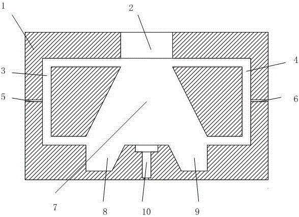
[0015] Such as figure 1 As shown, in the present invention, a jet inlet 2 is opened in the upper part of the valve body 1, a small to large conical oscillation cavity 7 is opened in the middle part, and a self-excited oscillation cavity 10 communicating with the oscillation cavity is opened in the lower part. The center of the cavity and the self-excited oscillation cavity 10 are located on the same axis; the left side of the valve body 1 is provided with a left feedback channel 3 which communicates with the end of the jet inlet 2 and the other end communicates with the left reflux cavity 8 at the bottom of the oscillation cavity. 1. On the right side, there is a right feedback channel 4 with one end communicating with the end of the jet inlet 2 and the other end communicating with the right reflux cavity 9 at the bottom of the oscillation cavity. The sides of the left r...


PUM


Abstract

The invention discloses an underwater crack corrosion jet nozzle. A jet flow inlet is formed in the upper portion in a valve, a conical oscillation cavity from small to large is formed in the middle in the valve, a self-oscillation cavity communicated with the oscillation cavity is formed in the lower portion in the valve, and the center of the jet flow inlet, the center of the oscillation cavity and the center of the self-oscillation cavity are all located on the same axis. A left feedback channel is formed in the left side of the valve, one end of the left feedback channel is communicated with the end of the jet flow inlet, and the other end of the left feedback channel is communicated with a left backflow cavity in the bottom of the oscillation cavity. A right feedback channel is formed in the right side of the valve, one end of the right feedback channel is communicated with the end of the jet flow inlet, and the other end of the right feedback channel is communicated with a right backflow cavity in the bottom of the oscillation cavity. A left capillary air hole communicated with the left feedback channel is formed in the left side of the valve, and a right capillary air hole communicated with the right feedback channel is formed in the right side of the valve. Two or more cavitation forms are combined, so that resonance is carried out in the valve to generate more bubbles, the capacity for the jet nozzle to generate cavitation is enhanced, and the washout effect of cavitation jet flow on a target is enhanced. The underwater crack corrosion jet nozzle can be used for cleaning the bottom of ship or an offshore production platform support.

Description

technical field [0001] The invention relates to a jet nozzle, in particular to an underwater cracking jet nozzle. Background technique [0002] Cavitation jet is in the high-speed water jet technology, which artificially generates and develops this kind of steam-filled cavitation, and controls the local high pressure generated when it breaks on the target object, which is used to strengthen its cleaning and crushing capabilities, thereby improving its Erosion properties. Many studies have shown that the cavitation in the fluid not only plays the role of transferring energy, but also has a high degree of energy accumulation. Under the mechanism of nonlinear action, the energy originally uniformly distributed in the flow field can be instantaneously concentrated in the vicinity of the cavitation. Very small area. Therefore, improving the ability of cavitation nozzles to generate cavitation is an important direction to enhance the erosion ability of cavitation jets. [0003]...

Claims


Application Information

Patent Timeline
Patent Type & Authority Applications(China)
IPC IPC(8): B05B1/34B05B7/04
CPCB05B1/3442B05B7/0416
Inventor 邹俊应泽吉晨杨华勇
Owner ZHEJIANG UNIV
Why Eureka
Try Eureka