Treatment chuck structure for facilitating negative-pressure adsorption
A suction cup and negative pressure technology, applied in the field of medical equipment, to achieve the effect of reducing production costs, simple structure, and convenient replacement
- Summary
- Abstract
- Description
- Claims
- Application Information
AI Technical Summary
Problems solved by technology
Method used
Image
Examples
Embodiment 1
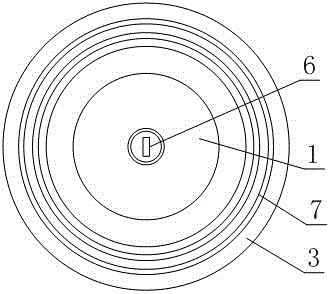
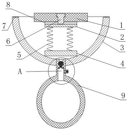
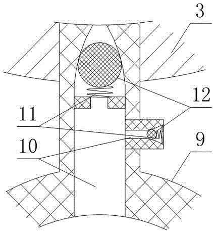
[0024] Such as Figure 1 to Figure 3 As shown, a suction cup structure for treatment that facilitates negative pressure adsorption includes a hemispherical suction cup body 3, and a hygroscopic body 1 is also arranged in the suction cup body 3, and the hygroscopic body 1 and the suction cup body 3 are connected by a spring 5 connected, and the hygroscopic body 1 and the suction cup body 3 form a detachable connection relationship, the suction cup body 3 is also provided with a negative pressure air bag 9, and the negative pressure air bag 9 is provided with two one-way valves, the negative pressure air bag 9 and The inner cavity of the suction cup body 3 is connected by a one-way valve, and the one-way valve allows the medium to flow from the inner cavity of the suction cup body 3 to the inner cavity of the negative pressure air bag 9, and the other one-way valve communicates with the inner cavity of the negative pressure air bag 9. The cavity and the outside world, and the on...
Embodiment 2
[0030] The present embodiment is further limited on the basis of embodiment 1, as Figure 1 to Figure 3 As shown, as a structural form that is convenient for disassembly and installation of the hygroscopic body 1 and is conducive to the uniform heating of the hygroscopic body 1, a spring seat 4 is also provided in the suction cup body 3, and one end of the spring 5 is fixedly connected to the spring seat 4. The other end of the spring 5 is fixedly connected with a screw seat 2, and the hygroscopic body 1 is connected with the screw seat 2 through a screw 6, and the heating sheet 8 is fixed on the screw seat 2, and the screw seat 2 is located between the heating sheet 8 and the hygroscopic body 1. between. Preferably, after the moisture absorbing body 1 and the screw seat 2 are fixed, the screw 6 is concave relative to the outer surface of the moisture absorbing body 1 .
[0031] As a structural form that facilitates the wearing stability of the suction cup body 3 , the axial ...
PUM
 Abstract
Description
Claims
Application Information
 - R&D
- Intellectual Property
- Life Sciences
- Materials
- Tech Scout
- Unparalleled Data Quality
- Higher Quality Content
- 60% Fewer Hallucinations
Browse by: Latest US Patents, China's latest patents, Technical Efficacy Thesaurus, Application Domain, Technology Topic, Popular Technical Reports.
© 2025 PatSnap. All rights reserved.Legal|Privacy policy|Modern Slavery Act Transparency Statement|Sitemap|About US| Contact US: help@patsnap.com


