
Terminal crimping device

A terminal crimping and terminal technology, which is applied in the direction of connection, electrical components, circuits, etc., can solve the problem of position deviation and achieve the effect of suppressing the generation of metal powder

Active Publication Date: 2015-12-09
SUMITOMO WIRING SYST LTD
View PDF7 Cites 2 Cited by
  • Summary
  • Abstract
  • Description
  • Claims
  • Application Information

AI Technical Summary

Problems solved by technology

[0004] However, in the case of this solution, it is easy to cause the continuous terminal to slightly shift its position in the conveying direction due to inertial motion when the conveying claw is stopped (excessive conveying), or to follow the movement of the conveying claw when returning the conveying hole. On the other hand, the position of the continuous terminal is shifted in the direction opposite to the conveying direction (return shift), etc.

Method used


Image

  • Terminal crimping device
  • Terminal crimping device
  • Terminal crimping device

Examples


no. 1 approach

[0063]

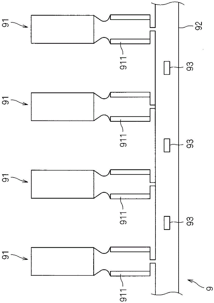
[0064] First, regarding the continuous terminal 9 as the object of the terminal crimping device 1, refer to figure 1 Be explained. figure 1 It is a plan view showing the continuous terminal 9 .

[0065] The continuous terminal 9 is a belt-shaped member in which a plurality of terminals 91 are connected. Specifically, a plurality of terminals 91 are formed in parallel at equal intervals on one side of a belt-shaped interlocking belt 92 . In the interlocking belt 92 , corresponding to the respective terminals 91 , transmission holes 93 are formed at equal intervals. A base portion (barrel portion) 911 of each terminal 91 is formed to be open in a substantially U-shaped cross section so that it can be crimped to an end portion of an electric wire.

[0066]

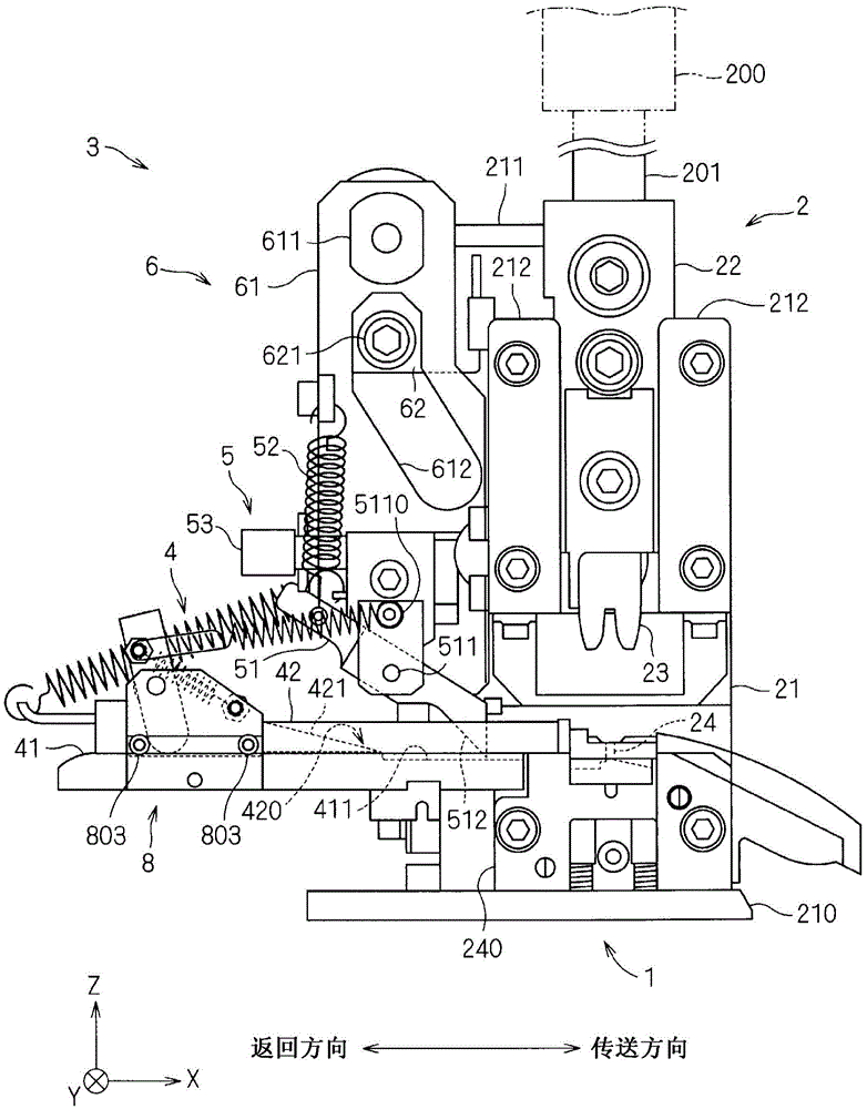
[0067] For the structure of the terminal crimping device 1, refer to figure 2 Be explained. figure 2 It is a schematic front view of the terminal crimping device 1 . It should be noted that, in figure ...

no. 2 approach

[0170] The terminal crimping device 1a of the second embodiment will be described. Figure 16 The schematic front view of the terminal crimping apparatus 1a of 2nd Embodiment is shown. The terminal crimping device 1a has the same structure as the terminal crimping device 1 of the first embodiment except that the structure of the one-side stopper is different. Furthermore, the operation of the terminal crimping device 1a is also the same as that of the terminal crimping device 1 of the first embodiment.

[0171]

[0172] The one-side brake unit (brake unit) 7 included in the terminal crimping apparatus 1 a brakes the movement of the continuous terminal 9 similarly to the one-side brake unit 8 in the above-mentioned embodiment. That is, the one-side stopper 7 is the same as the one-side stopper 8 of the above-mentioned embodiment, and the upstream side (-X side) of the transport claw 51 in the transport direction is connected to the continuous terminal 9 placed on the stage 4...


PUM


Abstract

An object of the present invention is to provide a technology for applying a proper crimping process to a terminal. To achieve this object, a terminal crimping device includes a one-sided braking unit for braking a movement of a series terminal. The one-sided braking unit includes a main body portion arranged to face the series terminal and a supporting portion for pivotably supporting the main body portion. A pivot axis of the main body portion is located upstream of a reference plane in a feed direction if a surface of the main body portion facing the series terminal is referred to as a facing surface and a virtual plane passing through a contact position of the facing surface with the series terminal and extending along a direction normal to a stage is referred to as the reference plane.

Description

technical field [0001] The present invention relates to a terminal crimping device for continuously crimping a terminal on an end of an electric wire. Background technique [0002] A terminal crimping device (terminal crimping applicator) is known as a device for continuously crimping terminals on the end of an electric wire. Generally, a terminal crimping device includes a delivery part that continuously sends out continuous terminals (a strip-shaped member formed by connecting a plurality of terminals) along a determined delivery path. The die fastens the terminal and crimps it to the crimping part of the electric wire, and the above-mentioned parts are linked together to perform the crimping process continuously (for example, refer to Patent Document 1). [0003] In the terminal crimping device, for example, claw-shaped members (feeding claws) are hooked to conveying holes formed at constant intervals in continuous terminals, and the conveying claws are moved in the conv...

Claims


Application Information

Patent Timeline
Patent Type & Authority Applications(China)
IPC IPC(8): H01R43/055
CPCB23P19/02B23P11/005H01R43/055
Inventor 土田太洋上田直之林晃司水谷达也
Owner SUMITOMO WIRING SYST LTD
Learn More