Method and device for cooling an engine

A motor and equipment technology, applied in the field of equipment for implementing the method, can solve the problems of time-consuming, system efficiency reduction, etc.

Inactive Publication Date: 2015-12-09
ROBERT BOSCH GMBH
View PDF7 Cites 2 Cited by
  • Summary
  • Abstract
  • Description
  • Claims
  • Application Information

AI Technical Summary

Problems solved by technology

[0007] Known methods for cooling the motor either lead to a loss of overall system efficiency, or are relatively complex and can only be achieved with additional lines and expansion valves, which also require separate adjustments

Method used


Image

  • Method and device for cooling an engine
  • Method and device for cooling an engine

Examples


Embodiment Construction

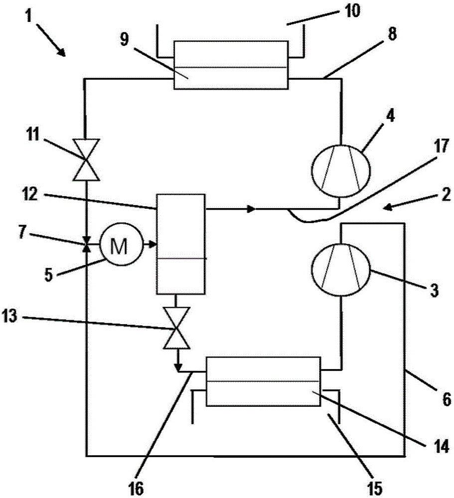
[0030] exist figure 1 A coolant circuit 1 of a heat pump with a two-stage compressor 2 comprising a first compression stage 3 and a second compression stage 4 is schematically shown in FIG. The two-stage compressor 2 is driven by a motor 5 , wherein the mechanical connection between the motor 5 and the compression stages 3 , 4 of the two-stage compressor 2 is not shown for the sake of clarity.

[0031] With the aid of the compression stages 3 , 4 of the two-stage compressor 2 , the pressure level of the coolant is first increased from a first pressure level to a medium average level and then to a high pressure level. In this case, a liquid fluid under excess pressure is used as coolant, which fluid is gaseous after depressurization and absorption of heat. The coolant is, for example, gaseous and is fed at low pressure to the first compression stage 3 of the compressor 2 and builds up there at an intermediate pressure level, wherein the coolant is heated at the same time.

[...


PUM


Abstract

The invention relates to a method and a device for cooling an engine, wherein the engine drives at least one at least two-stage compressor (2) of a refrigerant circuit (1), which compressor comprises at least a first compression stage (3) and a second compression stage (4), wherein a refrigerant is conducted through the refrigerant circuit (1), which refrigerant is raised from a low pressure level to a medium pressure level in the first compression stage (3) and from the medium pressure level to a high pressure level in the second compression stage (4) and, subsequently to the second compression stage (4), is expanded to the medium pressure level with a release of heat.

Description

technical field [0001] The invention relates to a method for cooling a motor according to the preamble of claim 1 and to a device for carrying out the method. Background technique [0002] Such a coolant circuit with a two-stage compressor is used, for example, in conjunction with a heat pump. In this case, the two compression stages of the compressor are driven by a motor, which is mechanically connected to the compressor for this purpose. A low to medium level of compression of the coolant gas is achieved by means of the first compression stage of the compressor. The pressure level is then further increased in the second compression stage until the coolant has a high pressure level. Heat can then be removed from the coolant via a condenser downstream of the second compression stage, the coolant is then decompressed and heat can be absorbed again in the evaporator for gaseous delivery to the first compression stage of the compressor. [0003] Depending on the mode of ope...

Claims


Application Information

Patent Timeline
IPC IPC(8): F25B31/00F25B1/10
CPCF25B1/10F25B31/006F25B2341/0662F25B2400/13F25B2400/23F25B41/39F25B31/026F25B49/025
Inventor M·迈泽S·克林克
Owner ROBERT BOSCH GMBH
Why Eureka
Try Eureka