Position detection device, position detection method, and moving body system

A detection device and a detection method technology, applied in the field of moving body systems, can solve the problems that the position of the magnetic pole cannot be detected, and high-precision and continuous position information cannot be obtained.

Active Publication Date: 2018-01-09
MURATA MASCH LTD
View PDF8 Cites 0 Cited by
  • Summary
  • Abstract
  • Description
  • Claims
  • Application Information

AI Technical Summary

Problems solved by technology

In addition, when there is a gap between the magnets on the track, the position detector provided on the moving body cannot detect the position of the magnetic pole between the gaps.
Therefore, the mobile body cannot obtain high-precision and continuous position information

Method used


Image

  • Position detection device, position detection method, and moving body system
  • Position detection device, position detection method, and moving body system
  • Position detection device, position detection method, and moving body system

Examples


Embodiment Construction

[0027] Hereinafter, embodiments of the present invention will be described with reference to the drawings.

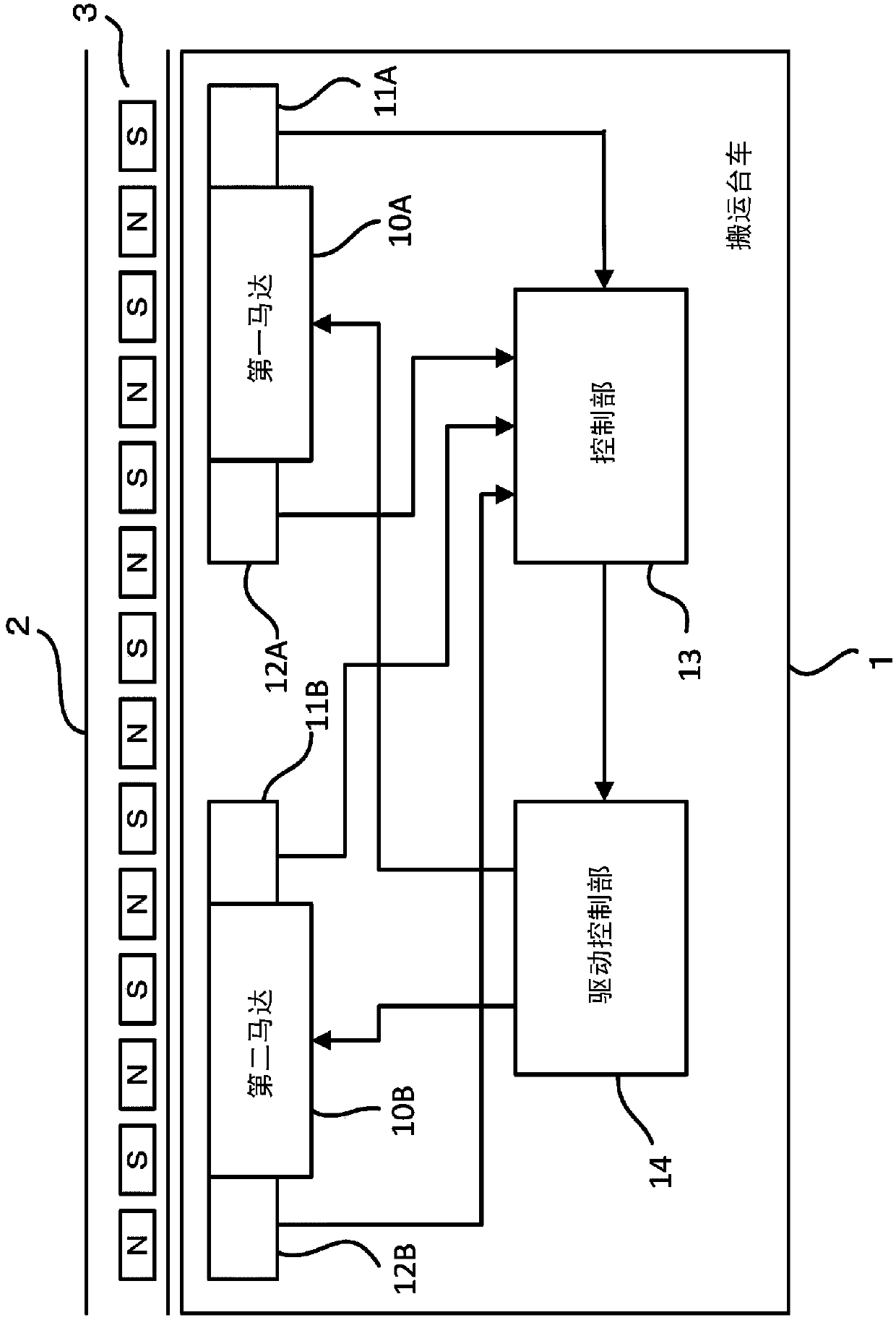
[0028] figure 1 It is a block diagram showing the mobile system of this embodiment. figure 1 The moving body system shown is a system using a ground quadratic linear motor. This moving body system includes a transport vehicle 1 as a moving body and a rail (guide rail) 2 as a moving path of the moving body. On the track 2 , magnets 3 with S poles and N poles are alternately arranged in a row at a predetermined pitch. also, figure 1 The mobile body system shown is, for example, a system of a ceiling traveling vehicle in which a transport vehicle 1 travels along a rail 2 provided on the ceiling. In addition, in this embodiment, the rail 2 is assumed as several kilometers, and the mobile body system which consists of 300 to 400 conveyance vehicles 1 is assumed. In addition, the moving body of this embodiment is not limited to the conveyance cart 1, and may be a moving ...


PUM


Abstract

The present invention relates to a position detection device, a position detection method and a moving body system, so that the distance of the moving path is not limited by the pitch of the magnet. The moving body (1) has: a first position detecting part (12A), which detects the position of the moving body (1) by detecting the magnetic pole of the magnet (3); a second position detecting part (12B), which detects the position of the moving body (1) It is arranged at a position different from that of the first position detection unit (12A) in the moving direction, and detects the position of the moving body (1). When the first position detection unit (12A) is located in an irregular section where the magnetic poles of the magnet (3) are irregularly arranged, the control unit (13) of the mobile body (1) based on the detection position of the second position detection unit (12B), Determine the position of the moving body (1).

Description

technical field [0001] The present invention relates to a position detecting device, a position detecting method, and a moving body system for detecting the position of a moving body moving along a moving path. Background technique [0002] Conventionally, a moving body system using a linear motor is known. Some of these moving body systems use ground quadratic linear motors. The ground quadratic formula is a system in which a linear motor is mounted on the movable element (moving body) side, and a magnet is arranged on the stationary element (rail) side. As such a moving body system, for example, a moving body system described in Patent Document 1 is known, in which magnets with S poles and N poles are alternately arranged on a track (moving path), and a moving body equipped with a linear motor moves along the track. move. Also, the moving body is provided with a position detection unit for detecting the position of the magnetic poles of the magnet. And, based on the de...

Claims


Application Information

Patent Timeline
Patent Type & Authority Patents(China)
IPC IPC(8): B60L13/03B65G54/02B61B13/06B61B13/08
CPCB60L13/03H02K11/215B60L15/005H02K41/031Y02T10/64G01D5/145G01D5/20
Inventor 山田康武东良行
Owner MURATA MASCH LTD
Why Eureka
Try Eureka