
Connector and assembly process thereof

A connector and junction technology, which is used in the assembly/disassembly of components, connections, and contacts of the connecting device, which can solve the problems of small creepage distance, small minimum distance, and large outer diameter of terminals, and meet short-circuit requirements. Guaranteed, reliable positioning and high consistency

Active Publication Date: 2015-12-09
HIGO TECH (SUZHOU) CO LTD
View PDF5 Cites 4 Cited by
  • Summary
  • Abstract
  • Description
  • Claims
  • Application Information

AI Technical Summary

Problems solved by technology

[0008] like Figure 4 As shown, there is a hanger at the end of the terminal, which is used to assemble with the reference surface of the positioning part, so the outer diameter of the terminal will be large, which leads to the minimum distance between adjacent terminals is too small, plus factors such as rosin brought in during welding, and then The creepage distance is small, which will cause a small proportion of the withstand voltage of the connector, and the insulation resistance does not meet the requirements, etc.
[0009] To sum up, the connectors in the prior art have problems such as unreliable terminal positioning, poor electrical performance and complicated assembly process.

Method used

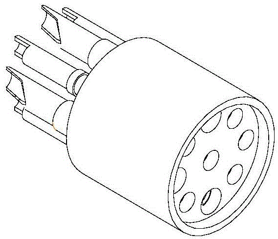
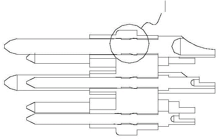
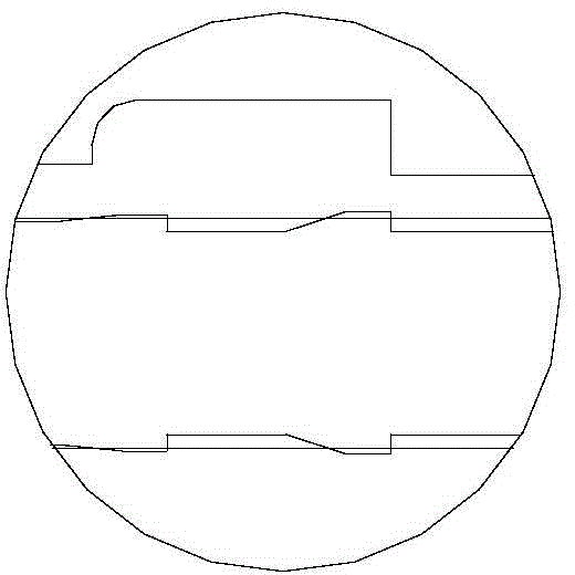

Image

  • Connector and assembly process thereof
  • Connector and assembly process thereof
  • Connector and assembly process thereof

Examples


Embodiment Construction

[0051] The present invention will be described in further detail below in conjunction with the accompanying drawings and embodiments. The implementation of the present invention is illustrated through specific specific examples below, and those skilled in the art can easily understand other advantages and effects of the present invention from the content disclosed in this specification.

[0052] It can be understood that the present invention can also be implemented or applied through other different specific embodiments, and the details in this specification can also be modified or changed based on different viewpoints and applications without departing from the spirit of the present invention. .

[0053] Figure 5 It is a schematic diagram of explosion decomposition of the connector in one embodiment of the present invention; Figure 6 for Figure 5 Schematic diagram of the general assembly of the connector.

[0054] to combine Figure 5 and Figure 6 As shown, the con...


PUM


Abstract

The present invention discloses a connector and an assembly process thereof. The connector comprises a male end side and a female end side. The male end side comprises pins, a first plum positioning member with the side-mounted arrangement of the pins, a male end positioning member which fixes the pins to the first plum positioning member, a first self-tapping screw which locks the male end positioning member and the first plum positioning member, and a male end shell. The female end side comprises jacks, a second plum positioning member with the side-mounted arrangement of the jacks, a female end positioning member which fixes the jacks to the second plum positioning member, a second self-tapping screw which locks the female end positioning member and the second plum positioning member, and a female end shell. The pins of the male end side and the jacks of the female end side are connected to form a connector. According to the connector the scheme, the reliable positioning of the pins and the jacks are ensured, the exposed size of the pins is guaranteed, the electrical performance is guaranteed, since pin and jack positioning connection structures are simplified, and thus the connector assembly process has the advantages of simple steps and high assembly precision.

Description

technical field [0001] The invention relates to a connector with reliable positioning, high electrical performance and simple assembly process. Background technique [0002] figure 1 It is a schematic diagram of a connection structure between a terminal and a positioning member in the prior art. [0003] Such as figure 1 As shown, the terminal is plugged and positioned on the terminal positioning piece first. Because the terminal and the positioning piece are assembled first and then welded, the adjacent terminals cannot be completely separated by a barrier, especially the solder cup part (which is not easy to weld). Heat-shrinkable sleeve: After the welding is completed, push the sleeve into place and then heat-shrink it. The effect of these two processes is poor in consistency (not easy to quantify), so there will be poor isolation of adjacent terminals, which cannot be fully guaranteed. [0004] It is also because the terminal and the positioning piece are first assemb...

Claims


Application Information

Patent Timeline
Patent Type & Authority Applications(China)
IPC IPC(8): H01R13/40H01R13/512H01R43/20
Inventor 周磊
Owner HIGO TECH (SUZHOU) CO LTD
Learn More