
Oil distribution structure with automatic gap compensation function

A technology of oil distribution and clearance, which is applied in the direction of fluid pressure actuation devices, fluid pressure actuation system components, mechanical equipment, etc., can solve the problems affecting the performance of drilling rigs, the reduction of working hydraulic oil flow, and the reduction of output efficiency, etc., and achieve structural Simple, time-saving, and easy-to-process effects

Active Publication Date: 2015-12-09
XIAN RES INST OF CHINA COAL TECH& ENG GROUP CORP
View PDF5 Cites 1 Cited by
  • Summary
  • Abstract
  • Description
  • Claims
  • Application Information

AI Technical Summary

Problems solved by technology

That is, the flow of working hydraulic oil in the parallel slewing circuit and clamping circuit is reduced, and the output efficiency is significantly reduced, which directly affects the performance of the drilling rig

Method used


Image

  • Oil distribution structure with automatic gap compensation function
  • Oil distribution structure with automatic gap compensation function
  • Oil distribution structure with automatic gap compensation function

Examples


Embodiment Construction

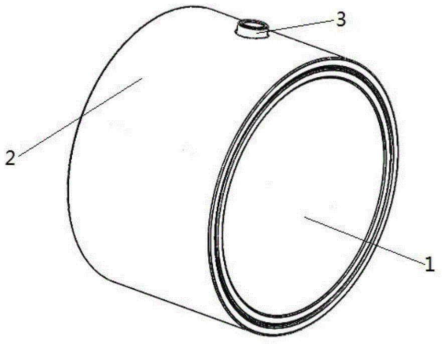
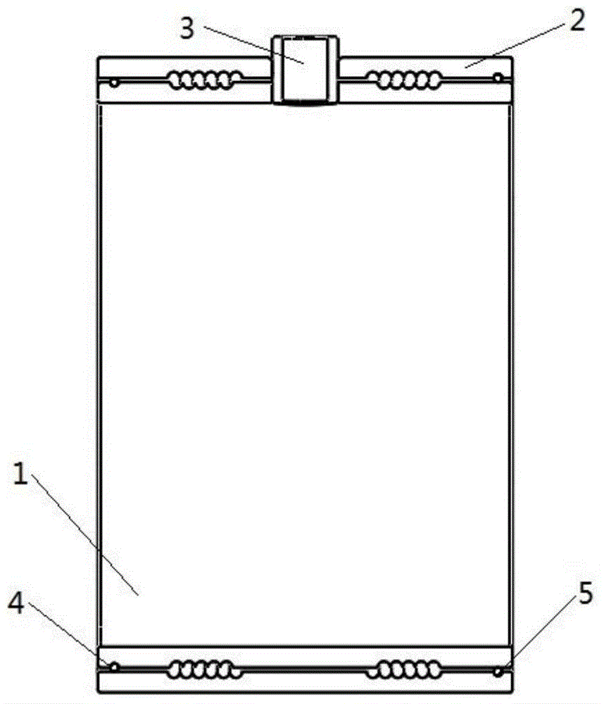
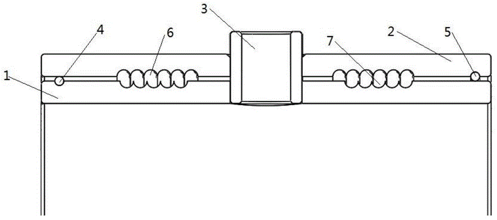
[0032] see Figure 1 to Figure 7 , showing the oil distribution structure with automatic clearance compensation of the present invention.

[0033] The oil distribution structure with automatic clearance compensation includes an oil distribution inner sleeve 1 and an oil distribution outer sleeve 2. The oil distribution inner sleeve 1 is cylindrical and can be sleeved on the main shaft of the drilling rig, and the oil distribution sleeve 2 is sleeved on the rig main shaft. The outer edge of the oil distribution inner sleeve 1.

[0034] In order to provide the entry of oil distribution, an oil inlet core pipe 3 is provided, and the oil inlet core pipe 3 is passed through the oil distribution inner sleeve 1 and the oil distribution outer sleeve 2 and can provide the entry of oil. The oil distribution inner sleeve 1 and the oil distribution inner sleeve 1 and The oil distribution jacket 2 is respectively provided with an inner jacket piercing hole 8 and an outer jacket piercing h...


PUM


Abstract

An oil distribution structure with the automatic gap compensation function comprises an inner oil distribution sleeve and an outer oil distribution sleeve. The inner oil distribution sleeve is cylindrical and a spindle is sleeved with the inner oil distribution sleeve. The inner oil distribution sleeve is sleeved with the outer oil distribution sleeve. The oil distribution structure is further provided with an oil inflow core pipe penetrating the inner oil distribution sleeve and the outer oil distribution sleeve. An oil inflow gap is formed between the inner oil distribution sleeve and the outer oil distribution sleeve. Sealing structures are arranged at the two ends of the oil inflow gap between the inner oil distribution sleeve and the outer oil distribution sleeve. The outer surface of the inner oil distribution sleeve is provided with at least one inner sleeve concave face. The inner surface of the outer oil distribution sleeve is provided with at least one outer sleeve concave face, wherein the outer sleeve concave faces correspond to the inner sleeve concave faces. Therefore, through clearance fit, when the spindle rotates at high speed, a hydrostatic bearing is formed by high-pressure oil in the gap between the spindle and the inner oil distribution sleeve, high-pressure oil between the inner oil distribution sleeve and the outer oil distribution sleeve guarantees that the gap between the inner oil distribution sleeve and the spindle is within the normal work range, and the abrasion of the spindle can be effectively reduced.

Description

technical field [0001] The invention relates to the technical field of drilling machinery accessories, in particular to an oil distribution structure with automatic clearance compensation. Background technique [0002] With the continuous improvement and development of hydraulic transmission technology in recent years, it has gradually replaced the traditional mechanical transmission method in the field of drilling machinery. Compared with mechanical transmission, hydraulic transmission can easily realize stepless speed regulation, has a large speed regulation range, and can be adjusted during the operation of the system; under the same power conditions, the hydraulic transmission device is small in size, light in weight and compact in structure. In the field of tunnel drilling rigs with high requirements on the external dimensions of drilling machinery, hydraulic transmission has almost completely replaced mechanical transmission. [0003] Tunnel drilling rigs used in dril...

Claims


Application Information

Patent Timeline
IPC IPC(8): F15B21/00
Inventor 殷新胜姚克邬迪孙保山张宏钧胡亚张哲杨江波
Owner XIAN RES INST OF CHINA COAL TECH& ENG GROUP CORP
Learn More