Intelligent speed-adjusting no-negative-pressure water supply equipment, water supply system and water supply control method

A technology of water supply equipment and intelligent speed regulation, which is applied in the direction of water supply pipeline system, water supply equipment, water conservation, etc., can solve the problems of low reliability and continuous water supply capacity of non-negative pressure water supply equipment, and achieve improved reliability and continuous water supply Ability to reduce the effect of burning damage

Active Publication Date: 2015-12-09
QINGDAO SANLI ZHONGDEMEI WATER EQUIP +1
View PDF7 Cites 2 Cited by
  • Summary
  • Abstract
  • Description
  • Claims
  • Application Information

AI Technical Summary

Problems solved by technology

[0003] The technical problem to be solved by the present invention is to provide an intelligent speed-regulating non-negative pressure water supply equipment, a water supply system and a water supply control method to solve the defects of low reliability and continuous water supply capacity of the non-negative pressure water supply equipment in the prior art, Improve the reliability and continuous water supply capacity of intelligent speed-regulating non-negative pressure water supply equipment

Method used


Image

  • Intelligent speed-adjusting no-negative-pressure water supply equipment, water supply system and water supply control method
  • Intelligent speed-adjusting no-negative-pressure water supply equipment, water supply system and water supply control method
  • Intelligent speed-adjusting no-negative-pressure water supply equipment, water supply system and water supply control method

Examples


Embodiment 1

[0053] Such as Figure 6-Figure 9 As shown, the variable frequency intelligent motor in this embodiment includes a casing 1, a stator 2, a rotor 3, a frequency conversion module 5 and a motor fan 6, the stator 2 and the rotor 3 are installed in the casing 1, the rotor 3 has a rotating shaft 31, and the casing 1 One end has an output end cover 11, the other end of the housing 1 has a non-output end cover 12, one end of the rotating shaft 31 is an output end 311, the other end of the rotating shaft 31 is a non-output end 312, and the output end 311 of the rotating shaft 31 extends out of the housing 1 The output end cover 11, the non-output end 312 of the rotating shaft 31 stretches out of the non-output end cover 12 of the housing 1, the motor fan 6 is fixed on the non-output end 312 of the rotating shaft 31, and the motor fan 6 is covered by the windshield 61. Among them, in order to highly integrate the controller 4 and the frequency conversion module 5 on the housing 1 and m...

Embodiment 2

[0058] Such as Figure 10-Figure 12 As shown, the variable frequency intelligent motor in this embodiment includes a casing 1, a stator 2, a rotor 3, a frequency conversion module 5 and a motor fan 6, the stator 2 and the rotor 3 are installed in the casing 1, the rotor 3 has a rotating shaft 31, and the casing 1 One end has an output end cover 11, the other end of the housing 1 has a non-output end cover 12, one end of the rotating shaft 31 is an output end 311, the other end of the rotating shaft 31 is a non-output end 312, and the output end 311 of the rotating shaft 31 extends out of the housing 1 The output end cover 11, the non-output end 312 of the rotating shaft 31 stretches out of the non-output end cover 12 of the housing 1, the motor fan 6 is fixed on the non-output end 312 of the rotating shaft 31, and the motor fan 6 is covered by the windshield 61. Among them, in order to highly integrate the controller 4 and the frequency conversion module 5 on the casing 1 and ...


PUM


Abstract

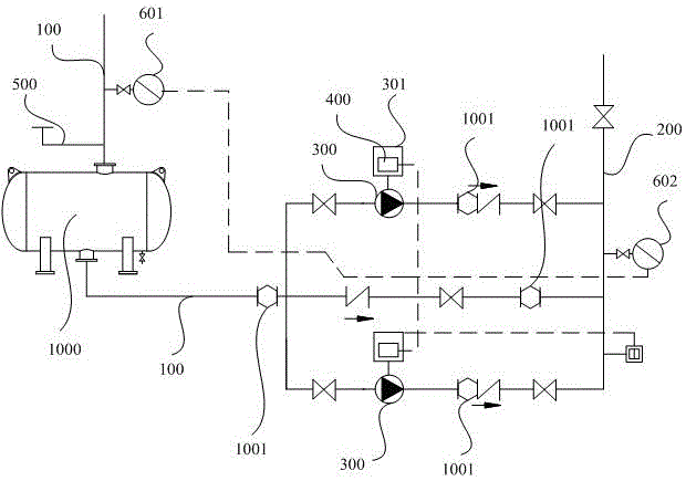
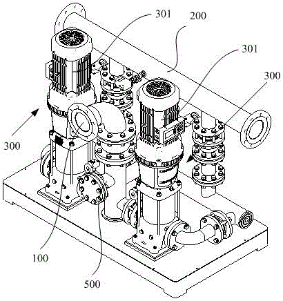
The invention discloses intelligent speed-adjusting no-negative-pressure water supply equipment, a water supply system and a water supply control method. The intelligent speed-adjusting no-negative-pressure water supply equipment comprises a main water inlet pipe, a main water outlet pipe, a steady-flow compensator, a water pump and a controller, wherein a function expansion pipe orifice which can be opened and closed is further arranged on the main water inlet pipe; a first pressure sensor is arranged on the main water inlet pipe; a second pressure sensor is arranged on the main water outlet pipe; the first pressure sensor and the second pressure sensor are connected with the controller separately. In the water supply control method, a dynamic water pressure adjusting mode and a water tank water supply mode are provided, the water supply stability and reliability can be improved, and the reliability and the continuous water supply capability of the intelligent speed-adjusting no-negative-pressure water supply equipment can be also improved.

Description

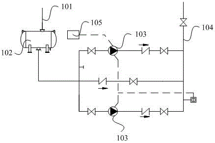
technical field [0001] The invention relates to the technical field of water supply, in particular to an intelligent speed-regulating non-negative pressure water supply equipment, a water supply system and a water supply control method. Background technique [0002] At present, non-negative pressure water supply equipment is widely used in people's daily life and industrial production, such as figure 1 As shown, the non-negative pressure water supply equipment in the prior art usually includes a main water inlet pipe 101, a water pump 103, a main water outlet pipe 104, and a control cabinet 105. The main water inlet pipe 101 is used to connect with the municipal pipe network to introduce tap water. The middle part of the water inlet pipe 101 has a steady flow compensator 102, the water inlet port of the water pump 103 is connected with the water outlet of the main water inlet pipe 101, the water outlet port of the water pump 103 is connected with the main water outlet pipe 1...

Claims


Application Information

Patent Timeline
Patent Type & Authority Applications(China)
IPC IPC(8): E03B11/16E03B7/07E03B7/09
CPCY02A20/00
Inventor 张明亮王学成吕廷顺高星福张凤岐
Owner QINGDAO SANLI ZHONGDEMEI WATER EQUIP
Why Eureka
Try Eureka