
Wheel-rail force strain gage fast and precise positioning device

A technology of precise positioning and positioning device, used in measuring devices, force/torque/work measuring instruments, instruments, etc., can solve the problems of low paste efficiency and low position accuracy, achieve precise position, easy and fast paste, and improve work efficiency and the effect of the accuracy of the test results

Active Publication Date: 2015-12-02
SOUTHWEST JIAOTONG UNIV
View PDF6 Cites 4 Cited by
  • Summary
  • Abstract
  • Description
  • Claims
  • Application Information

AI Technical Summary

Problems solved by technology

[0005] The invention aims to solve the problems of low position accuracy and low pasting efficiency existing in the pasting technology of wheel-rail force strain gauges

Method used


Image

  • Wheel-rail force strain gage fast and precise positioning device
  • Wheel-rail force strain gage fast and precise positioning device

Examples


Embodiment Construction

[0013] The structure of the present invention will be described in further detail below in conjunction with the accompanying drawings.

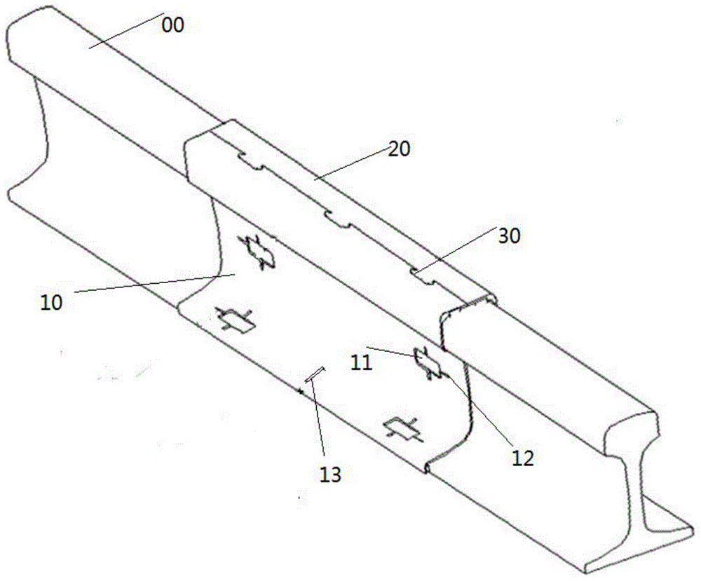
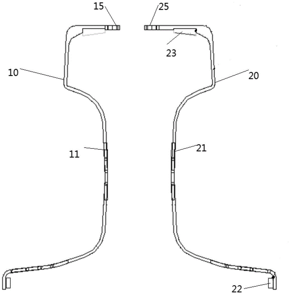
[0014] It can be seen from the figure that the positioning device is composed of two mirror-symmetric calibration plates, that is, a left calibration plate 10 and a right calibration plate 20 . The calibration plate has a shape consistent with the rail waist and rail bottom of the tested wheel and rail 00. Calibration holes, such as 11 and 21, are set on the calibration plate corresponding to the tested wheel-rail waist and rail bottom items, and the calibration holes can be set in multiple places as required. The middle part of the bottom surface of the calibration plate is provided with a centering hole 13 for observing and positioning to realize the correct placement of the calibration plate. The tops of the left calibration plate 10 and the right calibration plate 20 are provided with a buckle mechanism 30 to realize the coupling of the ...


PUM


Abstract

The invention discloses a wheel-rail force strain gage fast and precise positioning device. The wheel-rail force strain gage fast and precise positioning device is used for accurately determining the arrangement position of a strain gage on a wheel-rail in a wheel-rail research experiment. The positioning device is composed of two calibration plates which are in mirror symmetry and include a left calibration plate 10 and a right calibration plate 20; the calibration plates have the same contour structure as the rail web and rail bottom of a tested wheel-rail; calibration holes corresponding to the rail web and rail bottom of the tested wheel-rail are formed in the calibration plates; centering holes used for observing positioning to realize correct arrangement of the calibration plates are formed at the middle portions of the bottom surfaces of the calibration plates; and the tops of the left calibration plate 10 and the right calibration plate 20 are provided with clamping mechanisms 30 for realizing the connection of the two calibration plates. With the positioning device of the invention adopted, the calibration holes can be accurately positioned, and the steel rail strain gauge can be bonded fast and conveniently, and the position of the strain gauge can be precise, and working efficiency and the accuracy of test results can be improved.

Description

technical field [0001] The invention relates to the fields of railway engineering, track mechanics and vehicle-track coupling dynamics testing, in particular to fast and precise positioning and installation of strain gauges for rail wheel-rail force testing. Background technique [0002] Under the current experimental conditions, the positioning of wheel-rail force strain gauges mainly relies on simple tools such as rulers and pencils for manual positioning. Since the strain gauges for testing wheel-rail force have high requirements for position accuracy, and manual pasting requires a ruler to measure the distance and draw a paste Positioning and other steps, position errors will inevitably occur during the process, resulting in inaccurate final test results. Under this background, this fast and accurate positioning device for wheel-rail force strain gauges is designed. [0003] The pasting process of traditional strain gauges is inefficient, with cumbersome steps and low pr...

Claims


Application Information

Patent Timeline
Patent Type & Authority Applications(China)
IPC IPC(8): G01L5/00
Inventor 宋小林翟婉明吕天航蔡成标王开云赵春发高建敏裴承杰
Owner SOUTHWEST JIAOTONG UNIV
Learn More