Multi-cylinder rotary compressor and refrigeration device with same
A technology of rotary compressor and compression mechanism, applied in rotary piston machinery, rotary piston pump, mechanical equipment, etc., can solve the problem of insufficient improvement effect, and achieve the improvement of refrigeration capacity, compressor efficiency and suction efficiency. The effect of improving and enhancing the suction efficiency
- Summary
- Abstract
- Description
- Claims
- Application Information
AI Technical Summary
Problems solved by technology
Method used
Image

Examples
Embodiment 1
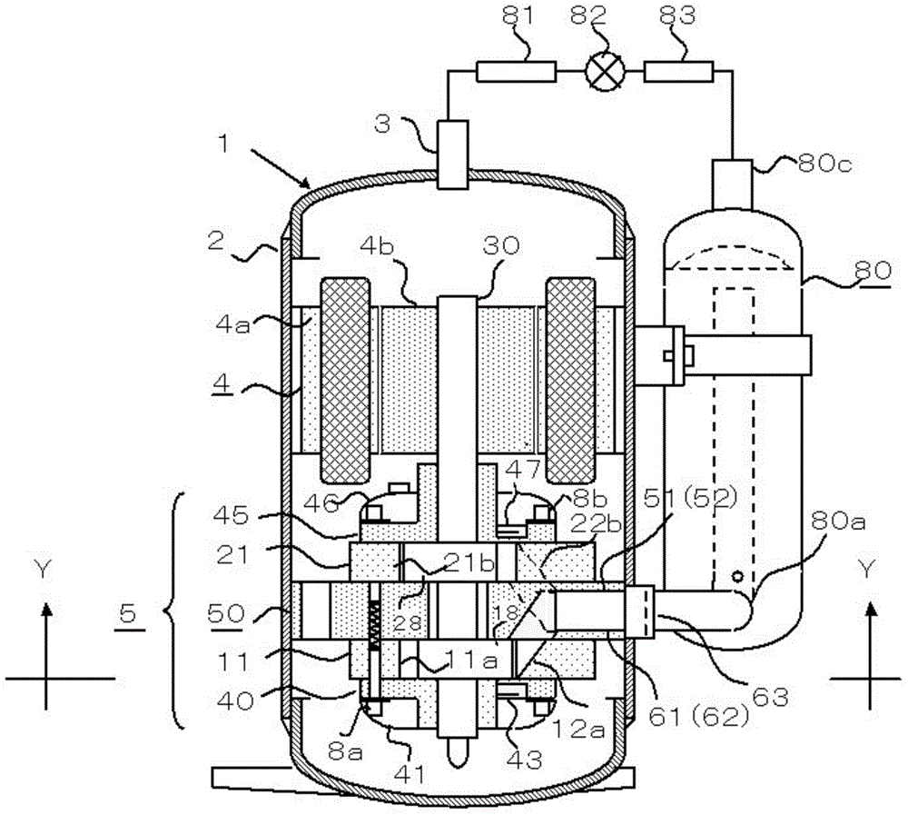
[0054] Such as figure 1 In the illustrated multi-cylinder rotary compressor 1 , the outer periphery of a stator 4 a constituting a motor 4 and the outer periphery of an intermediate partition 50 provided at the center of a compression mechanism unit 5 are fixed to the inner periphery of a housing 2 . The casing 2 is composed of a cylindrical casing and two end plates welded at its upper and lower ends. In addition, lubricating oil (oil) is stored at the bottom of the casing 2, but it is not shown in the figure.
[0055] The compression mechanism part 5 is provided with: the first air cylinder 11 and the second air cylinder 21 fixed in the middle partition plate 50, the first piston 18 and the second piston 28 accommodated in these air cylinders, and the first slide reciprocating together with these pistons. Sheet 16 and the second sliding sheet 26 ( Figure 4 Refer to), the first end plate 40 and the second end plate 45 connected to the opening surfaces of the first compress...
Embodiment 2
[0073] Figure 7 In order to increase the installation angle of the second cylinder 21 by 45 degrees, the angle θ of the two first slide grooves 13 and the second slide groove 23 is set to 90 degrees. As a result, the tapped holes 60a and 60b coincide, and four through tapped holes distributed at equal intervals of 90 degrees each are formed, so it is convenient for processing and assembling parts.
[0074] Furthermore, if the angle θ is increased to 180 degrees by increasing θ, the maximum values of the rotational torque generated by the two compression chambers will overlap, so the rotational torque is the same as that of the single cylinder, and the effect of mitigating the torque variation of the double cylinder is lost. Therefore, in order to maintain the obvious difference in the torque variation effect of the two cylinders, it can be determined that the upper limit of θ is 90 degrees.
Embodiment 3
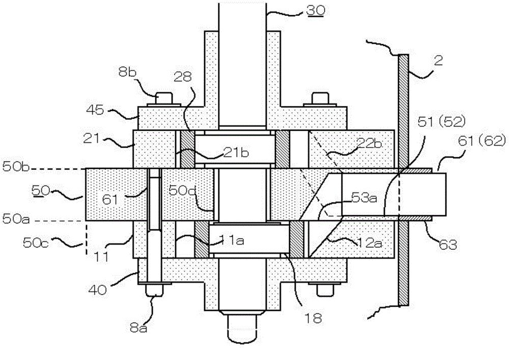
[0076] Figure 8 The thickness of the middle partition 50 is increased, and the first suction hole 51 and the second suction hole 52 are arranged in the vertical direction in the outer periphery 50c of the middle partition 50. Each suction circuit is independent and communicates with the first compression chamber 11a and the second compression chamber 11a. 2 Compression chamber 21b.
[0077] In Embodiment 3, the thickness of the middle partition 50 is increased, so the central hole 50d can be used as a bearing. In this design, the intermediate shaft 33 provided in the eccentric shaft 30 is a sliding fit with the central hole 50d. In addition, the angle θ of the two cylinders used in Embodiments 1 and 2 may be zero.
[0078] In addition, Embodiments 1 to 3 show the application of a two-cylinder compressor. Needless to say, these disclosure techniques can also be applied to a 3-cylinder compressor that requires two partitions, or a 4-cylinder compressor that requires three part...
PUM
 Abstract
Description
Claims
Application Information
 - R&D
- Intellectual Property
- Life Sciences
- Materials
- Tech Scout
- Unparalleled Data Quality
- Higher Quality Content
- 60% Fewer Hallucinations
Browse by: Latest US Patents, China's latest patents, Technical Efficacy Thesaurus, Application Domain, Technology Topic, Popular Technical Reports.
© 2025 PatSnap. All rights reserved.Legal|Privacy policy|Modern Slavery Act Transparency Statement|Sitemap|About US| Contact US: help@patsnap.com