Fixed point clutch shifting rod mechanism of slide wire

A sliding contact line and rod mechanism technology, which is applied to the control mechanism, power control mechanism, building structure, etc. of the wing fan, and can solve the problems affecting the normal operation of the side turnstile, damage to wires and cables, and unstable power supply contact. , to achieve the effect of solving unstable power supply contact, reducing maintenance rate and simple structure

Active Publication Date: 2015-12-02
JIANGSU JINQIUZHU GRP
View PDF6 Cites 0 Cited by
  • Summary
  • Abstract
  • Description
  • Claims
  • Application Information

AI Technical Summary

Problems solved by technology

[0002] Side revolving doors are generally used in warehouses and other occasions. Traditional electric revolving doors supply power. The trolley line is a curved track. When the collector walks on the curved rail, the power supply contact is prone to instability, and the drag chain or cable directly pulls the collector. The operation jamming, the long-term uneven force of the collector caused the damage of wires and cables, etc., thus affecting the normal operation of the side revolving door

Method used


Image

  • Fixed point clutch shifting rod mechanism of slide wire
  • Fixed point clutch shifting rod mechanism of slide wire
  • Fixed point clutch shifting rod mechanism of slide wire

Examples


Embodiment approach

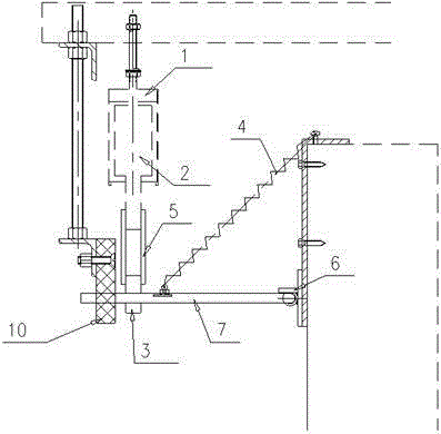
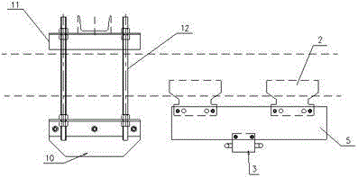
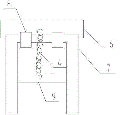
[0013] Such as Figure 1-3 An embodiment of the fixed-point clutch and lever mechanism of a sliding contact line of the present invention is shown: including the sliding contact line 1, the current collector 2, the drive block 3, the limit block 10 and the dial-back device. The collector 2 and the driving block 3 are provided with a clamping plate 5 on the outside. The collector 2 slides in the sliding contact line 1. A fixing plate 11 is provided at the upper end of the sliding contact line 1, and the limit stop 10 passes The connecting shaft 12 is connected with the fixed plate 11, the dial-back device is connected to the door leaf through the base 6, the driving block 3 is clamped on the dial-back device, and the dial-back device includes a U-shaped lever 7 and a connection A ring 8, the U-shaped lever 7 is connected to the base 6 through a connecting ring 8, a cross bar 9 is provided on the U-shaped lever 7, and one end of a tension spring 4 is connected to the cross bar 9,...


PUM


Abstract

The invention relates to a fixed point clutch shifting rod mechanism of a slide wire. The mechanism comprises the slide wire, a current collector, a driving check block, a limiting check block and a return shifting device; clamping plates are arranged at the outer side of the current collector and the outer side of the driving check block; the current collector slides in the slide wire; a fixing plate is arranged at the upper end of the slide wire; the limiting check block is connected with the fixing plate through connecting shafts; the return shifting device is connected to a door leaf through a base; the driving check block is connected to the return shifting device in a clamped mode; the return shifting device comprises a U-shaped shifting rod and connecting rings; the U-shaped shifting rod is connected with the base through the connecting rings; a cross rod is arranged on the U-shaped shifting rod; one end of a tension spring is connected to the cross rod; the other end of the tension spring is fixed to the door leaf. The fixed point clutch shifting rod mechanism of the slide wire has the advantages that the structure is simple, the design is reasonable, the installation is convenient, and it is guaranteed that the current collector is stressed uniformly and operates stably, so that the operation of a side swing door is facilitated, and the side swing door can operate more smoothly.

Description

technical field [0001] The invention relates to an automatic rod pulling mechanism for a sliding contact line of a side revolving door. Background technique [0002] Side revolving doors are generally used in warehouses and other occasions. Traditional electric revolving doors supply power. The trolley line is a curved track. When the collector walks on the curved rail, the power supply contact is prone to instability, and the drag chain or cable directly pulls the collector. The operation jamming, the electric wire and cable damage caused by uneven force on the collector for a long time, etc., thus affecting the normal operation of the side revolving door. Contents of the invention [0003] The purpose of the present invention is to overcome the above disadvantages and provide an automatic pull-out mechanism for sliding contact wires of side revolving doors that avoids running jams caused by drag chains or cables directly pulling collectors and can ensure smooth operation...

Claims


Application Information

Patent Timeline
IPC IPC(8): E05F15/608
Inventor 陈卫国王剑郭汉松
Owner JIANGSU JINQIUZHU GRP
Why Eureka
Try Eureka