Eureka AIR delivers breakthrough ideas for toughest innovation challenges, trusted by R&D personnel around the world.

Contact rear sleeve riveting tool

A technology for riveting tooling and contact parts, which is applied in the field of riveting tooling for the back cover of the contact part for connectors, and can solve problems such as low reliability, poor consistency of the contact parts, and the inability of crimping pliers to achieve the effect of riveting the contact end and the back cover. , to achieve the effect of stable and precise movement and improve versatility

Inactive Publication Date: 2015-12-02
CHINA NORTH IND GRP HANGLIAN TECH CO LTD
View PDF6 Cites 4 Cited by
  • Summary
  • Abstract
  • Description
  • Claims
  • Application Information

AI Technical Summary

Problems solved by technology

[0002] With the progress of the times and the development of society, electrical connectors are developing in the direction of high reliability and miniaturization, and the contacts are also developing in the direction of miniaturization. Because the contacts are too small, the original method of riveting the rear sleeve with crimping pliers is not applicable. , it is difficult to accurately locate the contact parts, and some crimping pliers cannot achieve the effect of riveting the contact end and the rear sleeve. Because it is manual operation, the degree of force is different, resulting in poor consistency and reliability of the riveted contact parts. high

Method used


Image

  • Contact rear sleeve riveting tool
  • Contact rear sleeve riveting tool
  • Contact rear sleeve riveting tool

Examples


Embodiment Construction

[0014] Below in conjunction with accompanying drawing, the specific embodiment of the present invention is described in further detail:

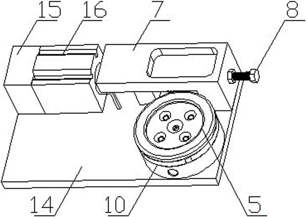
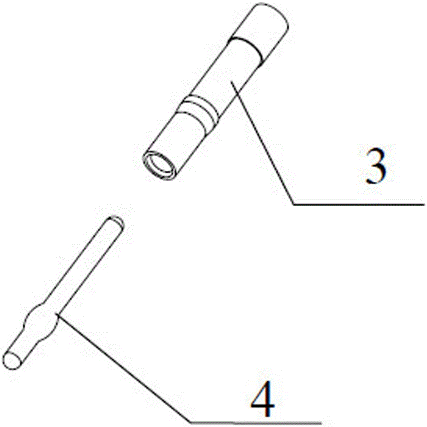
[0015] As shown in the figure, a riveting tool for the rear cover of a contact piece includes a base 14 on which a cylinder 16 and a riveting device are installed. There is a positioning through hole, and a positioning block 11 is movably installed in the positioning through hole, and the bottom of the positioning block 11 is supported by the base. The top surface of the slider round seat 10 is provided with a cylindrical boss 18 coaxial therewith, and the cylindrical boss 18 is provided with a horizontal cross groove 19 through which the center of the cross groove 19 communicates with the positioning through hole correspondingly. Four slide blocks 9 that cross are placed, the head of the slide block 9 is a pointed top, the tail of the slide block 9 is an arc surface and the tail of the slide block 9 stretches out of the cylindrical boss 18 ...


PUM


Abstract

The invention relates to a contact rear sleeve riveting tool comprising a base. A cylinder and a riveting device are mounted on the base. The riveting device comprises a slide block circular seat; the center of the slide block circular seat is provided with a positioning through hole; the top surface of the slide block circular seat is provided with a cylinder boss coaxial with the slide block circular seat; the cylinder boss is provided with horizontal cross recess penetrating the cylinder boss; the center of the cross recess is communicated with the positioning through hole; and four slide blocks in a cross structure are placed in the cross recess. The head of each slide block has a steeple top; the tail of each slide block has an arc surface; and the tail of each slide block extends from the outer side of the cylinder boss. A pressure spring arranged in the direction of the cross recess is arranged at the bottom of each slide block; one end of the pressure spring is connected to the corresponding slide block; and the other end of the pressure spring is fixedly connected to the slide block circular seat. The slide blocks simultaneously press a contact rear sleeve located in the positioning through hole of the slide block circular seat after the slide blocks move toward the center in the cross recess, and then the riveting is completed.

Description

technical field [0001] The invention relates to the field of electrical connectors, in particular to a riveting tool for a rear cover of a contact piece for a connector. Background technique [0002] With the progress of the times and the development of society, electrical connectors are developing in the direction of high reliability and miniaturization, and the contacts are also developing in the direction of miniaturization. Because the contacts are too small, the original method of riveting the rear sleeve with crimping pliers is not applicable. , it is difficult to accurately locate the contact parts, and some crimping pliers cannot achieve the effect of riveting the contact end and the rear sleeve. Because it is manual operation, the degree of force is different, resulting in poor consistency and reliability of the riveted contact parts. high. Contents of the invention [0003] In order to solve the problems in the prior art, the object of the present invention is...

Claims


Application Information

Patent Timeline
IPC IPC(8): B21D39/00
Inventor 叶学俊殷斌崔青云徐继华常新峰芮星季彩萍李竹法
Owner CHINA NORTH IND GRP HANGLIAN TECH CO LTD
Why Eureka
Eureka Blog
Learn More