
Control device of liquid outlet device

一种控制装置、出液通道的技术,应用在出液装置领域,能够解决传动部件需要清洗、操作便利性差、密封效果差等问题,达到降低零件的数量、确保洁净度、档次性提高的效果

Active Publication Date: 2015-12-02
FUJIAN DEHUA JIAFU PORCELAIN CO LTD
View PDF4 Cites 0 Cited by
  • Summary
  • Abstract
  • Description
  • Claims
  • Application Information

AI Technical Summary

Problems solved by technology

[0007] The purpose of the present invention is to provide a control device for a liquid outlet device to solve the problems of poor operation convenience, inconvenient cleaning and cleaning of transmission parts due to poor sealing effect in the prior art

Method used


Image

  • Control device of liquid outlet device
  • Control device of liquid outlet device
  • Control device of liquid outlet device

Examples


Embodiment Construction

[0040] In order to further explain the technical solution of the present invention, the present invention will be described in detail below through specific examples.

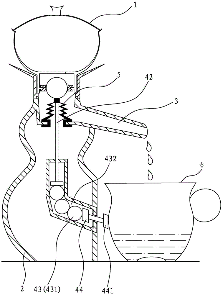
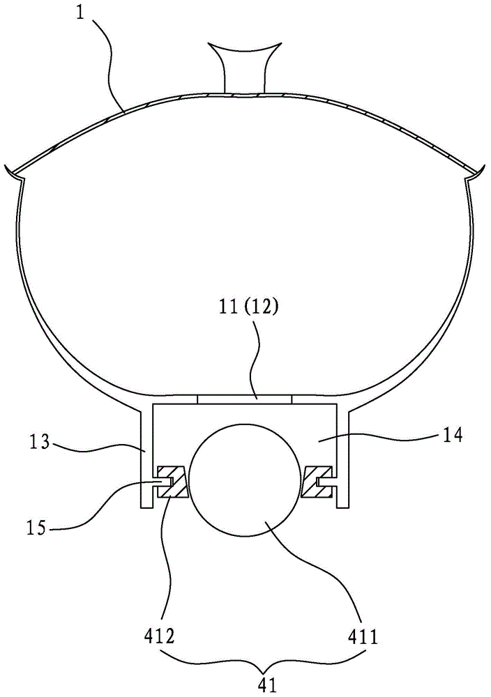
[0041] Such as Figure 1 to Figure 3 As shown, a liquid outlet device related to the present invention includes a pot body 1, a base 2, a liquid outlet channel 3, and a control device 4 for controlling the conduction or cutoff of the liquid outlet channel 3. The pot body 1 is arranged on the base 2 Above, the bottom of the pot body 1 is provided with a liquid outlet 11 communicating with the liquid outlet 3, and the liquid outlet 11 is provided with a filter 12; the above-mentioned technical features are basically the same as those of a conventional automatic liquid outlet device, and this application People will not describe in detail.

[0042] The improvement of the present invention is that the control device 4 has a valve assembly 41, a first push rod 42, a transmission mechanism 43 and a second push rod 4...


PUM


Abstract

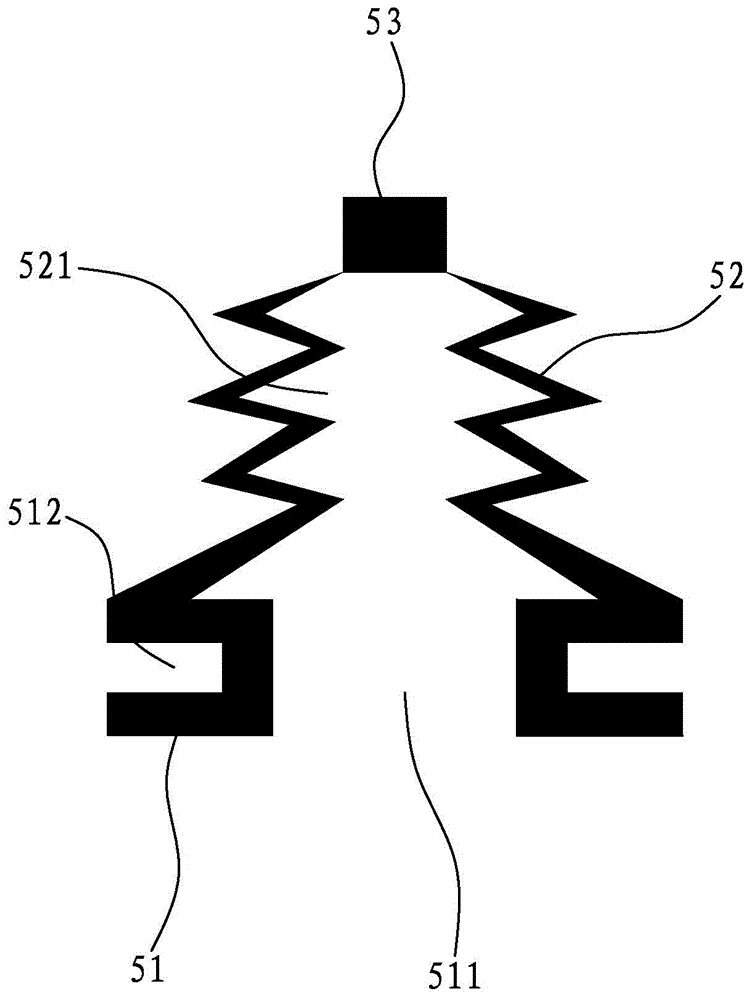
The invention discloses a liquid discharging device. The liquid discharging device comprises a pot body, a base, a liquid discharging channel and a control device used for controlling the liquid discharging channel to be connected or disconnected. The pot body is arranged on the base, a liquid discharging port communicated with the liquid discharging channel is formed in the bottom of the pot body, and a filter screen is arranged in the liquid discharging port. The control device is provided with a valve component located in the liquid discharging channel, a first push rod, a transmission mechanism and a second push rod, an opening is formed in the inner wall of the liquid discharging channel, an elastic silicon gel piece is arranged in the opening in a sealing mode, the upper end of the first push rod butts against the elastic silicon gel piece and controls the valve component to be opened and closed through the elastic silicon gel piece, the lower end of the first push rod is in transmission connection with the second push rod through the transmission mechanism, and a butting end capable of butting against a liquid receiving device is further formed on the second push rod. The liquid discharging device does not make direct contact with people in the whole process and avoids the problems such as scald, and the convenience and the level of the liquid discharging device are both improved greatly due to the fact that the liquid discharging device can achieve automatic liquid discharging.

Description

[0001] The patent application of the present invention is a divisional application of Chinese patent application number 201410069844.1, the original application number is 201410069844.1, the application date is February 27, 2014, and the invention name is a liquid outlet device. technical field [0002] The invention relates to the field of liquid outlet devices, and more specifically relates to a control device for a liquid outlet device that can realize automatic liquid outlet, self-cleaning and very easy to use. Background technique [0003] The application of the liquid outlet device as a teapot, wine pot and coffee pot is known. In the existing liquid outlet device, when pouring the liquid in the pot, it is necessary to pick up the whole teapot by hand to make the liquid in the pot flow out. Hands are easy to touch each part of the kettle body, and hygiene cannot be guaranteed, and if the kettle body is filled with liquid with too high temperature, the temperature outsid...

Claims


Application Information

Patent Timeline
Patent Type & Authority Applications(China)
IPC IPC(8): A47G19/14
Inventor 廖世芳
Owner FUJIAN DEHUA JIAFU PORCELAIN CO LTD
Learn More