Vehicle-mounted expert diagnosis method and system
A technology of expert diagnosis and fault diagnosis, which is applied in the field of expert diagnosis, can solve the problems of wasting labor costs and time costs, and cannot meet the needs of users' intelligence, and achieve the effect of meeting the needs of intelligence and reducing labor costs and time costs
- Summary
- Abstract
- Description
- Claims
- Application Information
AI Technical Summary
Problems solved by technology
Method used
Image
Examples
Embodiment 1
[0058] Embodiment 1 of the present application provides a vehicle-mounted expert diagnosis method, such as figure 1 as shown, figure 1 It is a flow chart of an on-board expert diagnosis method provided in Embodiment 1 of the present application. The method includes:
[0059] S101: Carry out fault monitoring on the vehicle in real time.
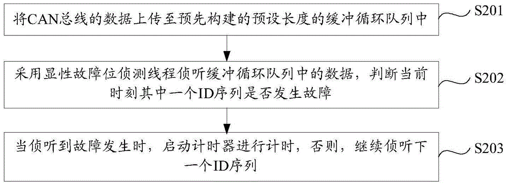
[0060] Specifically, such as figure 2 as shown, figure 2 It is a flow chart of a method for detecting faults of a vehicle in real time provided in Embodiment 1 of the present application. Specifically include:
[0061]S201: Upload CAN bus data to a pre-built buffer loop queue with a preset length.
[0062] In this application, it is necessary to pre-build a buffered circular queue with a length of N to save the scene. The specific length is not limited in this application, and can be set according to actual needs.
[0063] S202: Using the dominant fault bit detection thread to listen to the data in the buffer circular queue, and judg...
Embodiment 2
[0092] On the basis of Embodiment 1, Embodiment 2 of the present application provides another vehicle-mounted expert diagnosis method, which includes such as figure 1 In addition to the steps shown, after storing the fault data and fault occurrence time in the fault list in the form of a list, it also includes:
[0093] The data sources in the fault data that meet the preset time range are stored remotely and locally.
[0094] Specifically, such as Figure 4 as shown, Figure 4 It is a flow chart of an on-board expert diagnosis method provided in Embodiment 2 of the present application, Figure 4 about to figure 1 Step S102 in is replaced by:
[0095] S102: Obtain the fault data and start the timer when the fault is detected, store the fault data and the time of fault occurrence in the fault list in the form of a list, and store the data source of the fault data that meets the preset time range remotely and locally storage.
[0096] During the timing of the timer, if a n...
Embodiment 3
[0110] On the basis of Embodiment 1, Embodiment 3 of the present application provides an on-board expert diagnosis system, such as Figure 5 as shown, Figure 5 It is a schematic structural diagram of an on-board expert diagnosis system provided in Embodiment 3 of the present application. The system includes: a listening module 401, a first storage module 402 and a diagnosis module 403, wherein,
[0111] The listening module 401 is used to listen to the fault of the vehicle in real time.
[0112] Such as Figure 6 as shown, Figure 6 A schematic structural diagram of an interception module provided in Embodiment 3 of the present application, the interception module includes: a buffer cycle module 501, a fault interception module 502, and a judgment module 503, wherein,
[0113] The buffer circulation module 501 is configured to upload CAN bus data to a pre-built buffer circulation queue with a preset length.
[0114] The fault detection module 502 is configured to use the d...
PUM
 Abstract
Description
Claims
Application Information
 - R&D
- Intellectual Property
- Life Sciences
- Materials
- Tech Scout
- Unparalleled Data Quality
- Higher Quality Content
- 60% Fewer Hallucinations
Browse by: Latest US Patents, China's latest patents, Technical Efficacy Thesaurus, Application Domain, Technology Topic, Popular Technical Reports.
© 2025 PatSnap. All rights reserved.Legal|Privacy policy|Modern Slavery Act Transparency Statement|Sitemap|About US| Contact US: help@patsnap.com


