Rotary bunker

A rotary, silo technology, applied in the field of mechanical transmission, can solve the problems of increasing the hardware cost and failure rate of the device, the limited clearing capacity of the central part of the silo, and the large starting current, so as to avoid excessive starting current and save energy. Visible, increase the effect of the passing path

Active Publication Date: 2015-11-25
宁夏巨能机器人股份有限公司
View PDF5 Cites 2 Cited by
  • Summary
  • Abstract
  • Description
  • Claims
  • Application Information

AI Technical Summary

Problems solved by technology

However, when the silo starts to rotate with this structure, the load is heavy and the starting current is large, so special design of the drive components is required to increase the number of starting stages so that the starting current can be controlled within a reasonable range, which greatly increases the The hardware cost and failure rate of the entire device, in addition, this structure has limited ability to clear the central part of the silo

Method used


Image

  • Rotary bunker

Examples


Embodiment Construction

[0013] The standard parts used in the present invention can be purchased from the market, and the special-shaped parts can be customized according to the instructions and the accompanying drawings. The specific connection methods of each part adopt mature bolts, rivets, welding in the prior art , pasting and other conventional means, will not be described in detail here.

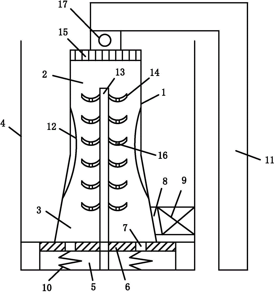
[0014] refer to figure 1 , the present embodiment includes a hopper 1, a driving motor 17 is connected with the hopper 1, and the hopper 1 includes a cylindrical first hopper part 2 and a conical second hopper part 3 arranged up and down, and the inner diameter of the second hopper part 3 is Gradually increasing from top to bottom, the outside of the hopper 1 is provided with a casing 4, the bottom surface of the casing 4 is provided with a slip ring 5, the top of the slip ring 5 is connected with a rubber damping groove 6, and the bottom of the hopper 1 is provided with a rubber damping groove 6. Stopper 7...


PUM


Abstract

The invention discloses a rotary bunker comprising a hopper and a driving motor connected with the hopper. The hopper is formed by a first cylindrical hopper part and a second tapered hopper part and the first and second hopper parts are arranged up and down; the external side of the hopper is provided with a housing; a slide ring is mounted on the bottom surface of the housing; a rubber damping groove is connected over the slide ring; the bottom of the hopper is provided with a baffle block inserted into the rubber damping groove; a discharging port tangent to the side wall is formed in the side surface of the second hopper part; the side wall of the housing is provided with a baffle plate cooperated with the discharging port; an exhaust port is formed in the bottom surface of the housing; the bottom of the baffle block is provided with a spring; the hopper is slideably mounted on a rack via a bearing; an elastic metal inner sleeve is disposed in the hopper; a gap is reserved between elastic metal inner sleeve and the side wall of the hopper; and a stirring pile independent to the hopper and connected with the housing is disposed in the center of the hopper. Deficiencies in the prior art can be improved by the use of the rotary bunker, and driving components are simplified, so block removing capability of the whole bunker is improved.

Description

technical field [0001] The invention relates to the technical field of mechanical transmission, in particular to a rotary feed bin. Background technique [0002] When conveying small granular materials, silos are often used. In order to reduce the probability of blockage during the use of the silo, the prior art improves the traditional silo. Chinese invention patent CN203237627U discloses a kind of arch-breaking and blockage-clearing rotary silo, through forced rotation, the blocked parts in the silo are cleared. However, when the silo starts to rotate with this structure, the load is heavy and the starting current is large, so special design of the drive components is required to increase the number of starting stages so that the starting current can be controlled within a reasonable range, which greatly increases the The hardware cost and failure rate of the whole device. In addition, this structure has limited ability to clear the blockage at the center of the silo. ...

Claims


Application Information

Patent Timeline
IPC IPC(8): B65D90/00B65D88/68
Inventor 宋明安王小龙孙洁同彦恒李志博麻辉
Owner 宁夏巨能机器人股份有限公司
Why Eureka
Try Eureka