
A vertical lathe turning force measuring device

A measuring device and vertical lathe technology, applied in turning equipment, auxiliary devices, manufacturing tools, etc., can solve the problems of inconvenient cutting force data analysis, inconvenient cutting force measurement, inconvenient force measuring instrument, etc., and achieve short measurement preparation time , good rigidity and rapid instrument installation

Inactive Publication Date: 2017-08-11
TIANJIN UNIV OF COMMERCE
View PDF8 Cites 0 Cited by
  • Summary
  • Abstract
  • Description
  • Claims
  • Application Information

AI Technical Summary

Problems solved by technology

[0003] Usually the cutting force of the vertical lathe is indirectly estimated by observing the current fluctuation of the spindle motor of the machine tool, the result is not accurate, there is a time lag, and it is not convenient for the data analysis of the cutting force
However, the cutting force is directly measured by the cutting force measuring instrument. Since the force measuring instrument is inconvenient to be directly installed on the tool holder of the vertical lathe, it is inconvenient to measure the cutting force.

Method used


Image

  • A vertical lathe turning force measuring device
  • A vertical lathe turning force measuring device
  • A vertical lathe turning force measuring device

Examples


Embodiment Construction

[0018] The present invention will be described in further detail below in conjunction with the accompanying drawings and specific embodiments.

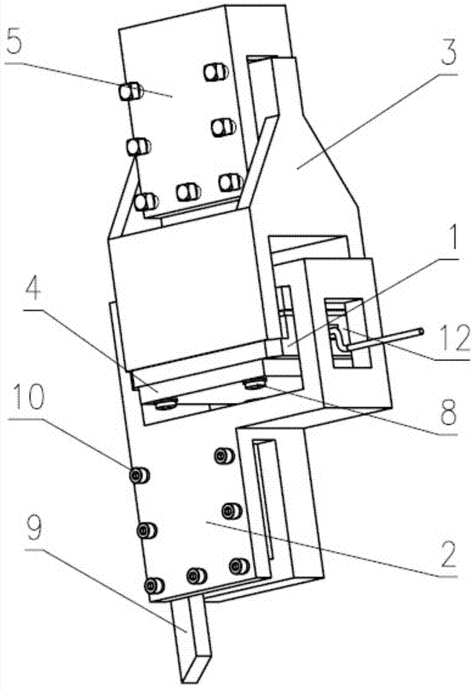
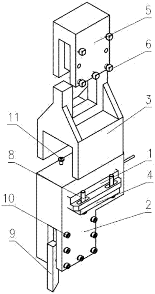
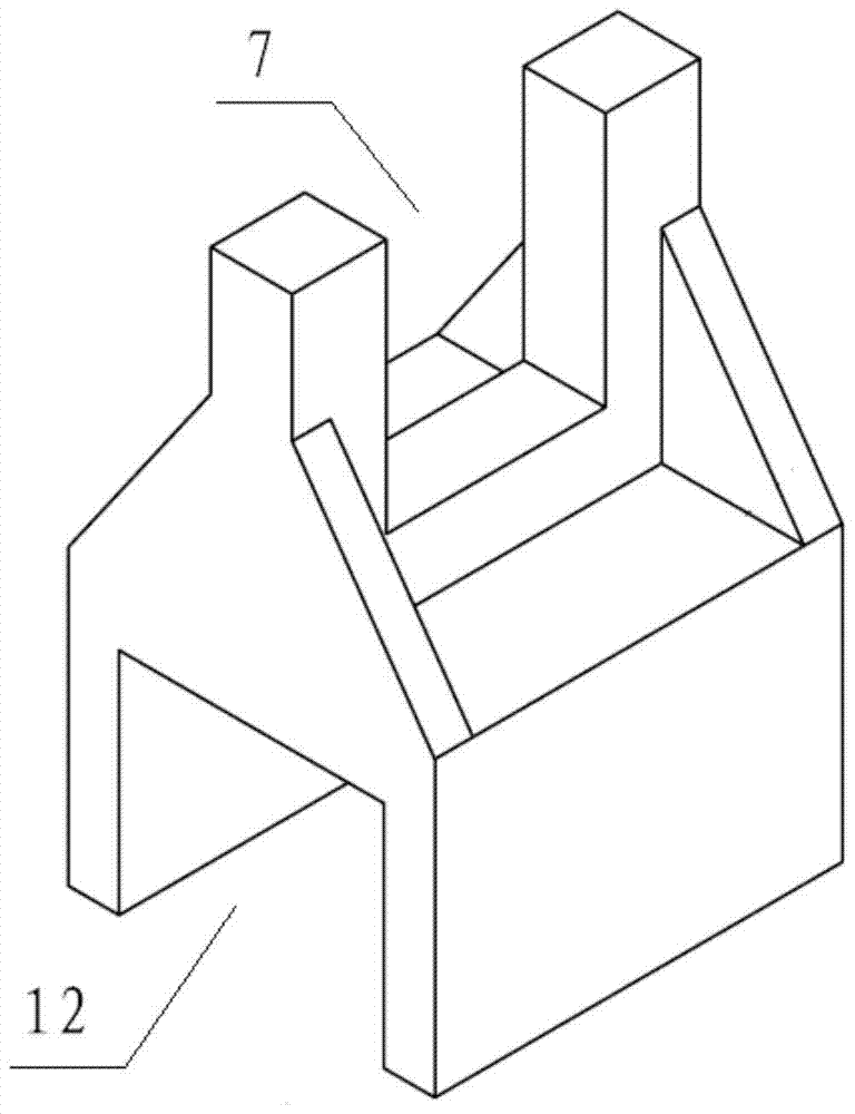
[0019] The schematic diagram of vertical lathe turning force measuring device of the present invention is as Figure 1-Figure 5 As shown, it includes a connecting seat 3 , a cutting dynamometer 1 , a base plate 4 and a tool holder 2 , the upper end of the connecting seat 3 is fixedly connected with the turning tool holder 5 , and a U-shaped opening 12 is provided at the lower end of the connecting seat 3 . The tool fixing frame 2 is composed of an integral square frame 13 and a square block 14 , and a tool mounting groove 15 is arranged on the square block 14 . The cutting dynamometer 1 and the bottom plate 4 are fixed on the lower end of the U-shaped opening 12 of the connecting seat, the square frame 13 of the tool holder 2 is placed in the U-shaped opening 12, and the square frame 13 is A dynamometer installation hole 16 is provid...


PUM


Abstract

The invention discloses a measurement device for turning force of a vertical lathe. The measurement device is simple in structure, convenient to use, practical and high in measurement precision. A U-shaped opening is formed in the lower end of a connection base. A tool fixing rack is composed of a square framework and a square block which are integrated. The square block is provided with a tool mounting groove. A cutting force measuring instrument and a bottom board are fixed to the lower end of the U-shaped opening of the connection base. The square framework of the tool fixing rack is arranged in the U-shaped opening. A force measuring instrument mounting hole is formed in the square framework. The measuring portion of the cutting force measuring instrument is arranged in the force measuring instrument mounting hole of the square framework in the U-shaped opening of the connection base. The upper surface of the cutting force measuring instrument is fixedly connected with the square framework. The square framework is provided with an outgoing line hole, and a connection cable of the cutting force measuring instrument is led out of the outgoing line hole. A turning tool is fixedly installed in the tool mounting groove. By means of the reasonable structural design, the measurement device is installed rapidly, the measurement preparing time of the whole device is short, and the measurement device is simple in structure, good in rigidity, convenient to use and high in precision.

Description

technical field [0001] The invention relates to the technical field of machining, and more specifically relates to a turning force measuring device for a vertical lathe. Background technique [0002] In order to study the process parameters of vertical lathe and improve the efficiency of vertical lathe turning, it is necessary to measure the dynamic cutting force in the process of turning tool in real time. [0003] Usually the cutting force of the vertical lathe is indirectly estimated by observing the current fluctuation of the spindle motor of the machine tool, the result is not accurate, there is a time lag, and it is not convenient for the data analysis of the cutting force. However, the cutting force is directly measured by the cutting dynamometer. Because the dynamometer is inconvenient to be directly installed on the tool holder of the vertical lathe, it is inconvenient to measure the cutting force. Contents of the invention [0004] The purpose of the present inv...

Claims


Application Information

Patent Timeline
Patent Type & Authority Patents(China)
IPC IPC(8): B23B25/06
CPCB23B25/06B23B2270/483
Inventor 王勇张晓川王小利马涛文邓江方雅阁张强张润佳彭东亭
Owner TIANJIN UNIV OF COMMERCE
Learn More