
Circuit board aligning method

A circuit board and together technology, applied in the field of circuit board manufacturing, can solve the problem of epoxy resin boards being unable to align

Active Publication Date: 2015-11-18
KINWONG ELECTRONICS TECH LONGCHUAN
View PDF4 Cites 4 Cited by
  • Summary
  • Abstract
  • Description
  • Claims
  • Application Information

AI Technical Summary

Problems solved by technology

[0003] In view of the deficiencies in the prior art, the purpose of the present invention is to provide a circuit board alignment method that solves the problem that the epoxy resin board is smaller than the working board and cannot be aligned.

Method used


Image

  • Circuit board aligning method
  • Circuit board aligning method

Examples


Embodiment Construction

[0021] The present invention will be further described below in conjunction with accompanying drawing and specific embodiment:

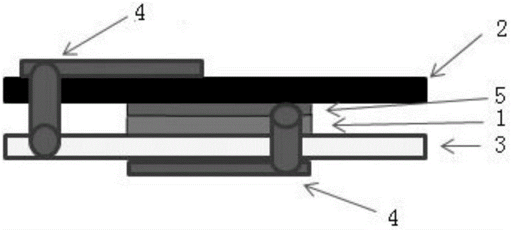
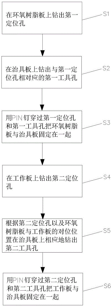
[0022] Such as Figure 1~2 As shown, the circuit board alignment method of the present invention uses the fixture board 3 to assist the alignment of the epoxy resin board 1 with inconsistent size and the working board 2, and the alignment pre-stacking process includes the following steps:

[0023] S1. Drill two first positioning holes on the epoxy resin board 1, assuming that the diameter of the first positioning holes is 2.45mm.

[0024] S2. Drill two first tool holes corresponding to the first positioning hole on the fixture plate 3. The aperture of the first tool hole is 0.05mm smaller than the aperture of the first positioning hole, that is, 2.4mm. The PIN nail passing through the first positioning hole and the first tool hole is better fixed to the jig plate 3 , and can easily pass in and out with the epoxy resin plate 1 .

[0025] S3. Use a P...


PUM


Abstract

The invention relates to the circuit board manufacture field, especially to a circuit board aligning method. The method includes drilling a first positioning hole in an epoxy resin plate, drilling a first tool hole, in a tool plate, corresponding to the first positioning hole, fixing the epoxy resin plate and the tool plate together through pins passing through the first positioning hole and the first tool hole, drilling a second positioning hole in a working plate, correspondingly drilling a second tool hole in the tool plate according to the second positioning hole and the aligning position of the epoxy resin plate and the working plate, and fixing the working and the tool plate together through pins passing through the second positioning hole and the second tool hole. The tool plate is respectively fixed with the epoxy resin plate and the working plate, and the epoxy resin plate is aligned and overlapping with the working plate indirectly. The problems of inconsistency of the sizes of the epoxy resin plate and the working plate and impossibility of aligning with the working plate when the epoxy resin plate is smaller than the working plate can be solved.

Description

technical field [0001] The invention relates to the field of circuit board manufacturing, in particular to a circuit board alignment method. Background technique [0002] In conventional lamination, the size of the epoxy resin board and the working board are the same, and the single-sided single-layer and single-sided multi-layer are laminated directly after the epoxy resin board, the medium layer, and the working board are laminated, and the sandwich is multi-layered. The board uses the riveting holes on the edge of the board to position the different layers with rivets and then presses them together. However, when the epoxy resin board is smaller than the working board, and there is no connection between the epoxy resin board and the working board, then It cannot be pre-stacked in a conventional way. At the same time, the alignment tolerance between the epoxy resin board and the working board is required to be + / -0.1mm, and the manual operation tolerance cannot be controll...

Claims


Application Information

Patent Timeline
Patent Type & Authority Applications(China)
IPC IPC(8): H05K3/46H05K3/00
CPCH05K1/0266H05K3/0008H05K3/4638H05K2203/0214H05K2203/0221H05K2203/15H05K2203/167
Inventor 张飞龙
Owner KINWONG ELECTRONICS TECH LONGCHUAN
Learn More