
A power distribution cabinet

A cabinet frame and electrical cabinet technology, applied in the electric power field, can solve the problems of unsafe, no protective lines, inconvenient wiring, etc., and achieve the effect of convenient fixing and convenient wiring.

Active Publication Date: 2017-05-10
STATE GRID ZHEJIANG LANXI POWER SUPPLY +4
View PDF5 Cites 0 Cited by
  • Summary
  • Abstract
  • Description
  • Claims
  • Application Information

AI Technical Summary

Problems solved by technology

Its disadvantage is that when installing electrical components in the distribution cabinet, it is inconvenient to route the wires, and there is no structure for protecting the circuit, which is not safe.

Method used


Image

  • A power distribution cabinet
  • A power distribution cabinet
  • A power distribution cabinet

Examples


Embodiment 1

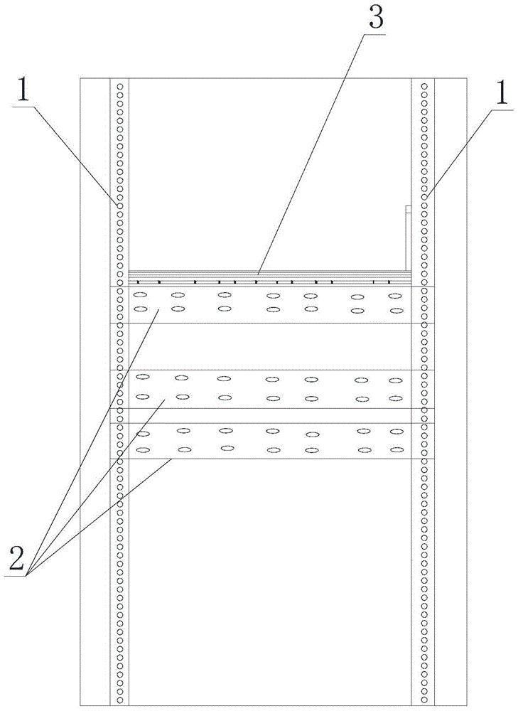
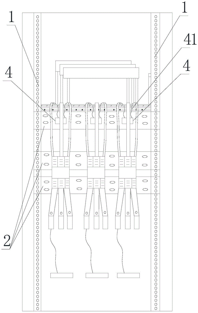
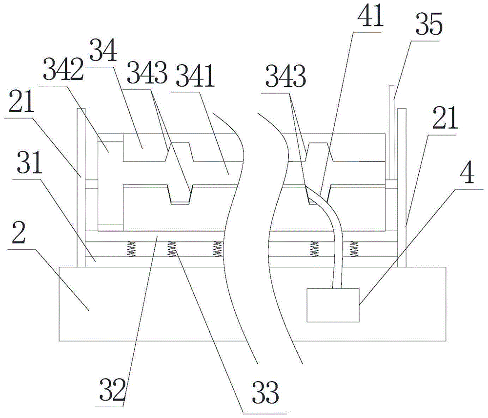
[0024] Such as Figure 1 to Figure 8 As shown, a power distribution cabinet frame of the present invention includes several longitudinal beams 1 and several cross beams 2, the longitudinal beams 1 and the cross beams 2 are connected to each other to form the main body of the electric cabinet frame, and the longitudinal beams 1 and the cross beams 2 are flexibly connected through connectors. The longitudinal beam 1 includes at least two connecting surfaces of the longitudinal beam 1 perpendicular to each other, and several longitudinal beam connecting holes are arranged in the longitudinal direction on the connecting surface of the longitudinal beam 1. Several stringer connection holes are arranged transversely on the connection surface. Such a structure is convenient to be connected and fixed with the line pipe 34, wherein at least one crossbeam 2 is provided with a fixing part 3, and the fixing part 3 includes a first horizontal plate 31 arranged on the upper end of the cross...

Embodiment 2

[0028] Such as Figure 9 , Figure 10 As shown, the difference from Embodiment 1 is that the connecting piece 21 on the side of the rotating rod 35 is provided with a movable fixing part for fixing the rotating rod 35 in the horizontal direction, and the fixing part fixes or loosens the rotating rod by moving 35. Such a structure can fix the rotating rod 35 and prevent it from disturbing to affect the stability of the overall structure. At the same time, the flat part 344 can be omitted, which simplifies the structure and increases the storage capacity of the connecting wires.

[0029] In order to prevent the connecting wire from the wire inlet 343 on the rear side of the cutout 341 moving to the wire inlet 343 on the front side of the cutout 341, the connecting wire and the fixed line part will be stuck, the wire inlet 343 on the front side of the cutout 341 is larger than the cutout 341 The wire inlet 343 on the rear side.

[0030] By implementing the present invention, t...


PUM


Abstract

The present invention aims to solve the problems in the prior art and find a power distribution cabinet with convenient and safe routing. The invention provides a power distribution cabinet frame which comprises multiple longitudinal beams and multiple cross beams. At least one cross beam is provided with a wire fixed part which comprises a first cross plate arranged at the upper end of the cross beam. A second cross plate is arranged above the first cross plate which is connected to the second cross plate through a spring. The upper end of the second cross plate is provided with a laterally disposed wire placement tube for placing a conductive wire, and two ends of the wire placement tube are sealed. Two ends of the cross beams are provided with upwardly projecting connecting pieces. One end of the wire placement tube is rotatingly connected to the connecting piece at the left side of a corresponding cross beam, and the other end is rotatingly connected to the connecting piece at the right side of the corresponding cross beam. The upper part of the wall of the wire placement tube is provided with a laterally disposed strip-shaped cut. One end of the wire placement tube is connected to a rotation rod which is perpendicular to the wire placement tube. After the rotation rod controls the wire placement tube to rotate for 180 degrees, the cut is just close to the second cross plate, the wire placement tube is provided with a wire outlet, and the front and back sides of the cut are provided with a plurality of wire inlets.

Description

technical field [0001] The invention belongs to the field of electric power, and in particular relates to a power distribution cabinet frame. Background technique [0002] The invention with the publication number of 202797615U discloses a power distribution cabinet frame, which includes several longitudinal beams and several cross beams. The longitudinal beams and cross beams are connected to each other to form the main body of the electric cabinet frame. There are several longitudinal beam connection holes arranged longitudinally on the longitudinal beam connection surface; the beam includes at least two mutually perpendicular beam connection surfaces, and several longitudinal beam connection holes are arranged transversely on the beam connection surface. Longitudinal beam connecting holes; the longitudinal beam and the cross beam are flexibly connected through the connecting piece. The utility model is provided with a lot of connection holes on the longitudinal beam and ...

Claims


Application Information

Patent Timeline
Patent Type & Authority Patents(China)
IPC IPC(8): H02B1/01H02B1/20
Inventor 姚侃吴建平
Owner STATE GRID ZHEJIANG LANXI POWER SUPPLY
Learn More