A dynamic display clock
A dynamic display and clock technology, which is applied to mechanically driven clocks to visually indicate the time, clocks and other directions, can solve the problems of monotonous display of mechanical clocks, and improve viewing, avoid monotony, and improve accuracy. The effect of showing time
- Summary
- Abstract
- Description
- Claims
- Application Information
AI Technical Summary
Problems solved by technology
Method used
Image
Examples
Embodiment 1
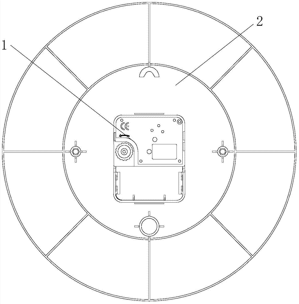
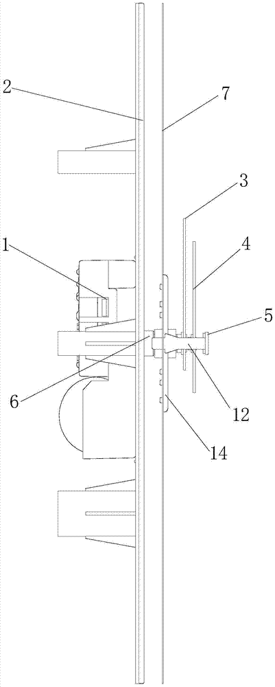
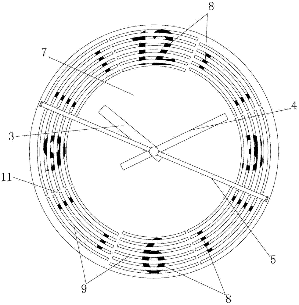
[0028] Such as Figure 1 to Figure 6 The shown dynamic display clock includes a movement 1, a base plate 2, an hour hand 3, a minute hand 4 and a second hand 5, the movement 1 is installed on one side of the base plate 2, and the hour hand 3, minute hand 4 and second hand 5 are all installed on The other side of the base plate 2, and the hour hand 3, the minute hand 4 and the second hand 5 are all connected to the movement 1 through the rotating shaft 6; side, and the turntable 7, hour hand 3, minute hand 4 and second hand 5 are distributed sequentially from the direction away from the bottom plate 2, the second hand 5 is connected to the turntable 7; the turntable 7 is provided with a plurality of slots, the other of the bottom plate 2 Time marks 8 corresponding to the slot holes are provided on the side surface.
[0029] The slots are arc slots 9, and a plurality of arc slots 9 are divided into four groups, and these four groups of arc slots 9 are evenly distributed around ...
Embodiment 2
[0039] This dynamic display clock increases the following technical features on the basis of Embodiment 1: as Figure 7 and Figure 8 As shown, the slots are straight slots 15, and the extension direction of the straight slots 15 is consistent with the radial direction of the turntable 7, that is, the center of the turntable 7 is radially evenly distributed, and the straight slots 15 are Groove width gradually increases from the axial direction away from the rotating disk 7; the middle of the base plate 2 is provided with a plurality of graphics 16, the shapes of the multiple graphics 16 are consistent, and the centers of the multiple graphics 16 are consistent, and the size of the multiple graphics 16 is in the range of The center is the base point and gradually increases along its radial direction; the multiple graphics 16 are made up of multiple strip-shaped color blocks 17 , and the color blocks 17 correspond to the straight slots 15 .
[0040] The figure 16 is heart-shap...
Embodiment 3
[0045] This dynamic display clock adds the following technical features on the basis of Embodiment 2: the shape of the graphic is a five-pointed star.
[0046] The principle of dynamically displaying the clock in this embodiment is the same as that in Embodiment 2, only the shape of the graph is different. This diversifies the styles of the clock and further enhances the decorative effect of the hour hands.
PUM
 Abstract
Description
Claims
Application Information
 - R&D
- Intellectual Property
- Life Sciences
- Materials
- Tech Scout
- Unparalleled Data Quality
- Higher Quality Content
- 60% Fewer Hallucinations
Browse by: Latest US Patents, China's latest patents, Technical Efficacy Thesaurus, Application Domain, Technology Topic, Popular Technical Reports.
© 2025 PatSnap. All rights reserved.Legal|Privacy policy|Modern Slavery Act Transparency Statement|Sitemap|About US| Contact US: help@patsnap.com


