Hole digging machine realizing anchoring through being driven by air pressure cylinder

A pneumatic cylinder and hole digging machine technology, applied in the direction of rotary drilling rigs, drilling equipment and methods, drilling equipment, etc., can solve the problem of increasing equipment costs and use costs, difficulty in adapting to construction conditions and requirements, and will not be well applicable Digging operations and other problems, to achieve the effect of increasing flexibility, increasing diameter, reducing thread lead angle

Inactive Publication Date: 2015-11-18
黄爱娟
View PDF5 Cites 4 Cited by
  • Summary
  • Abstract
  • Description
  • Claims
  • Application Information

AI Technical Summary

Problems solved by technology

[0004] This method tends to increase equipment cost and use cost
[0005] And some machinery in other fields will not be well suited for the digging operation in the above situation
Moreover, the flexibility of the equipment used for its operation is poor, and it is difficult to adapt to different construction conditions and requirements.

Method used


Image

  • Hole digging machine realizing anchoring through being driven by air pressure cylinder
  • Hole digging machine realizing anchoring through being driven by air pressure cylinder
  • Hole digging machine realizing anchoring through being driven by air pressure cylinder

Examples


Embodiment Construction

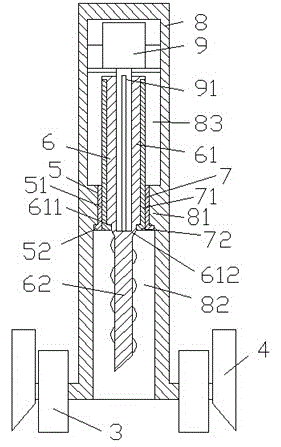
[0012] Combine below Figure 1-3 The present invention will be described in detail.

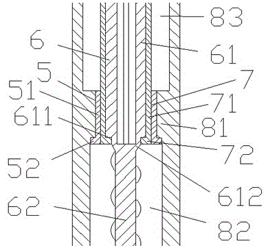
[0013] According to the embodiment, the hole digging machine driven and anchored by a pneumatic cylinder includes an outer casing 8, a driving motor 9 and a drilling rod part 6 driven by the driving motor 9, wherein the driving motor 9 is arranged on the outer casing The drive motor 9 is in the body 8 and the drive motor 9 is axially slidably coupled with the spline hole in the drive sleeve part 61 of the digging drill rod part 6 through the spline rod 91 fixedly connected. The driving sleeve part 61 of the drill rod part 6 is fixedly connected with the drill rod part 62 of the drilling rod part 6 through the tapered connection part 612, and the outer peripheral surface of the driving sleeve part 61 is provided with an axially extending key for connecting with The axially extending keyway on the inner peripheral wall of the cylinder 71 of the externally threaded sleeve part 7 fits, and the l...


PUM


Abstract

The invention provides a hole digging machine realizing anchoring through being driven by an air pressure cylinder. The hole digging machine comprises an outside casing (8), a driving motor (9) and a hole digging drill pipe component (6), wherein the hole digging drill pipe component (6) is driven by the driving motor (9); the driving motor (9) is arranged inside the outside casing (8) and is in axially gliding power connection with a spline hole formed in a driving sleeve part (61) of the hole digging drill pipe component (6) through a fixedly connected spline rod (91); the driving sleeve part (61) of the hole digging drill pipe component (6) is fixedly connected with a drill pipe part (62) of the hole digging drill pipe component (6) through a gradually reduction connecting part (612); and an axial extending key is arranged on the outer peripheral surface of the driving sleeve part (61) and is used for being matched with an axial extending key slot formed in the inner peripheral wall of a tube body (71) of an external threaded sleeve component (7).

Description

technical field [0001] The application relates to the field of construction machinery, in particular to a hole digging machine driven and anchored by a pneumatic cylinder. Background technique [0002] In some construction sites, such as garden construction, road construction and building construction, some hole digging operations are often required, and a hole digger is needed in this case. [0003] Hole digging operations are often carried out on soil floors. Some existing hole digging machines need to be manually controlled in the case of small-scale construction, and in the case of large-scale construction, they need to be controlled by a mechanical arm to provide the mechanical force for pressing down and make the pressing down follow the depth of the hole. And keep the pressure on. [0004] This way tends to increase equipment cost and use cost. [0005] And some machinery in other fields will not be suitable for the digging operation of above-mentioned situation we...

Claims


Application Information

Patent Timeline
IPC IPC(8): E21B3/00
Inventor 黄爱娟
Owner 黄爱娟
Why Eureka
Try Eureka