Width-adjustable mobile platform and robot with same
A mobile platform, wide-format technology, used in the field of robotics
- Summary
- Abstract
- Description
- Claims
- Application Information
AI Technical Summary
Problems solved by technology
Method used
Image
Examples
Embodiment 1
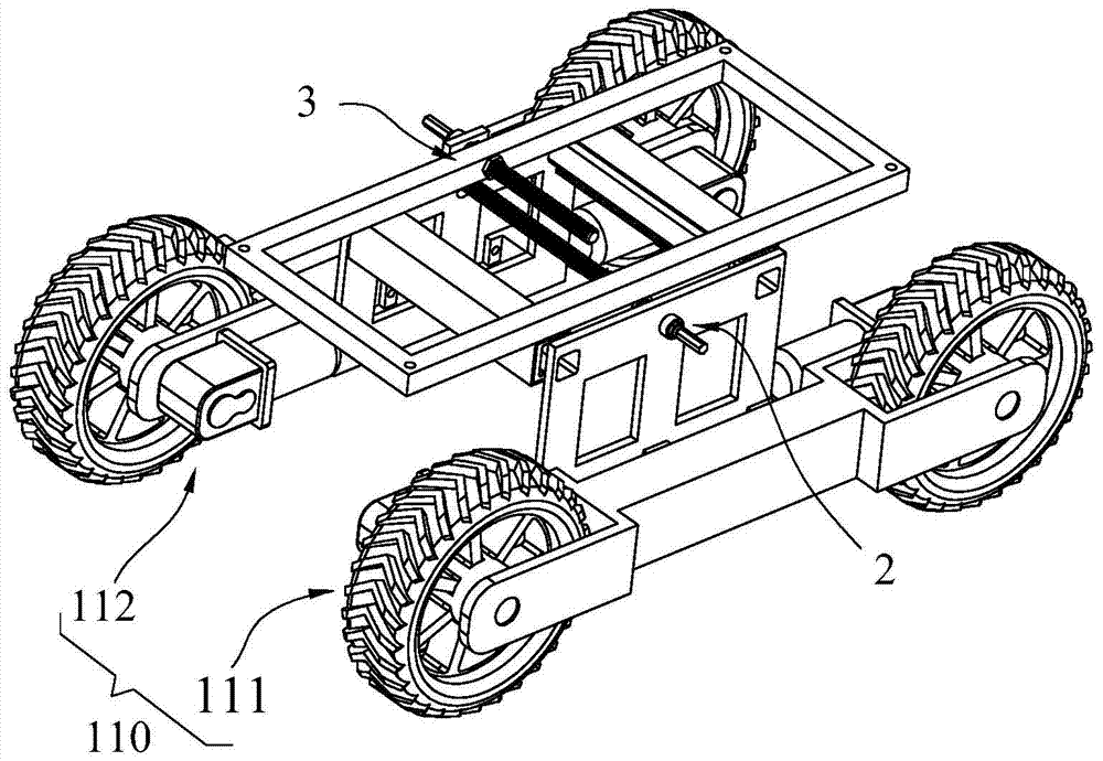
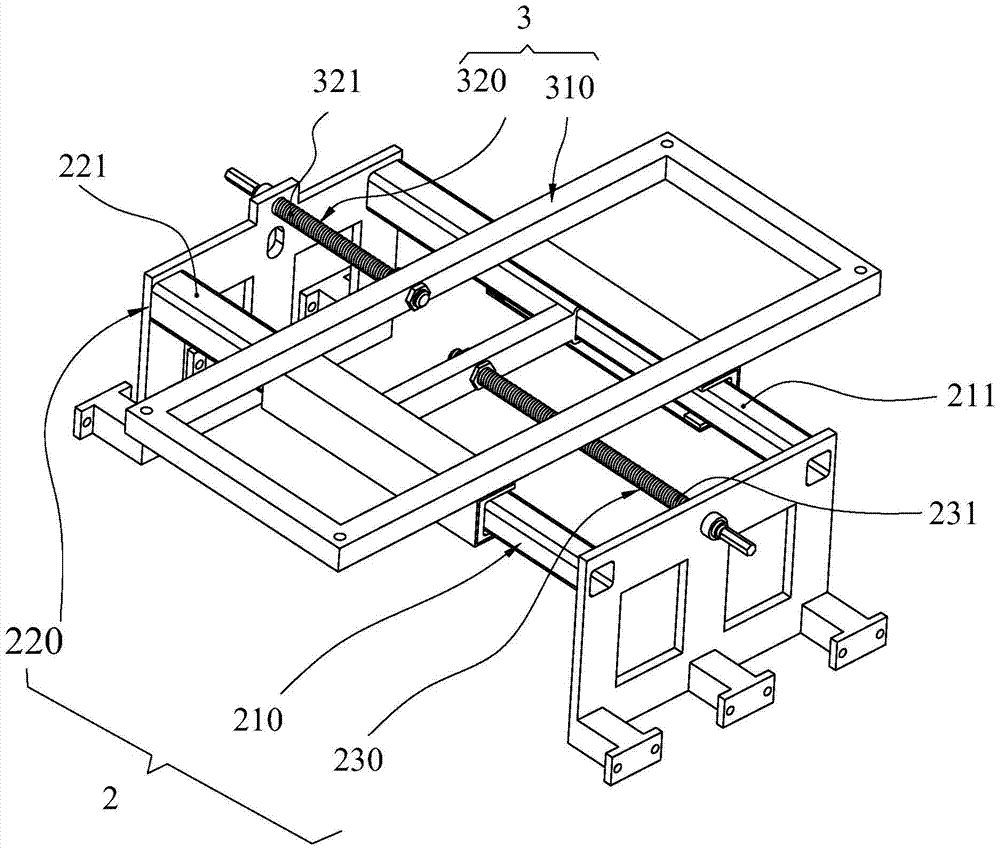
[0088] refer to Figure 1 to Figure 8 ;
[0089] The technical solution adopted by the present invention to solve its technical problems is:
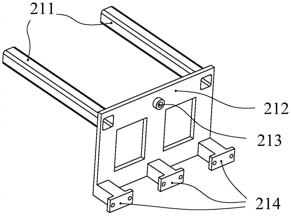
[0090] figure 1 , 6 7. The width-adjustable mobile platform according to Embodiment 1 of the present invention includes: a running part, a width adjusting device 2 and a centering device 3 ; in this embodiment, the running part is a wheeled running part 110 . The wheeled running part 110 includes a running part frame, and there are two wheeled running parts 110 in a symmetrical structure, and the wheeled running part 110 includes a first wheeled running part 111 and a second wheeled running part 112 . Such as figure 2 As shown, the width adjusting device 2 is located between the first wheeled running part 111 and the second wheeled running part 112 and is connected with the first wheeled running part 111 and the second wheeled running part 112, and the width adjusting device 2 Including: screw rod frame 210, the screw rod frame 21...
Embodiment 2
[0100] refer to Figure 10 to Figure 11 ;
[0101] Such as Figure 10 , 11 As shown, the difference between the second embodiment of the present invention and the first embodiment is that the amplitude modulation screw unit also includes a first drive unit 232, and the first drive unit 232 is connected with the amplitude modulation screw 231 and drives the amplitude modulation screw The rod 231 rotates; the centering screw rod unit includes a second driving unit 322, which is connected to the centering screw rod 321 and drives the centering screw rod 321 to rotate. In this embodiment, both the first drive unit 232 and the second drive unit 322 use geared motors. In other embodiments, other rotary driving devices such as hydraulic motors, pneumatic motors, etc. may be selected. Figure 10 is the state diagram when the width is the smallest in Embodiment 2 of the present invention; Figure 11 It is the state diagram when the width is the largest in Embodiment 2 of the prese...
Embodiment 3
[0103] refer to Figure 12 to Figure 13 ;
[0104] Figure 12 In the third embodiment, one end of the amplitude modulation screw 231 of the amplitude modulation screw unit 230 is fixedly connected with the screw frame 210; Pivotally connected, and the amplitude modulation moving screw nut 215 is connected with the amplitude modulation screw rod 231 with a threaded pair; one end of the centering screw rod 321 of the centering screw rod unit 320 is fixedly connected with the hole frame 220 (in other embodiments, One end of the centering screw rod 321 is fixedly connected with the screw mandrel frame 210); the centering frame 310 includes a centering moving screw nut 315, and the centering moving thread nut 315 is pivotally connected with the centering frame 310, and the centering The screw mandrel 321 is connected with the moving screw nut 315 in the adjustment with a thread pair. In the third embodiment, the width adjusting device further includes a first driving assembly 24...
PUM
 Abstract
Description
Claims
Application Information
 - Generate Ideas
- Intellectual Property
- Life Sciences
- Materials
- Tech Scout
- Unparalleled Data Quality
- Higher Quality Content
- 60% Fewer Hallucinations
Browse by: Latest US Patents, China's latest patents, Technical Efficacy Thesaurus, Application Domain, Technology Topic, Popular Technical Reports.
© 2025 PatSnap. All rights reserved.Legal|Privacy policy|Modern Slavery Act Transparency Statement|Sitemap|About US| Contact US: help@patsnap.com


