Meter lathe for shifting guide shaft processing

An instrument lathe and lathe technology, applied in metal processing equipment, metal processing machinery parts, turning equipment, etc., can solve the problems of affecting processing efficiency, lack of precise adjustment, difficulty in grasping the depth of the upper cavity of the workpiece, etc., to improve processing accuracy and Efficiency, the effect of avoiding operational errors

Inactive Publication Date: 2015-11-18
CHONGQING YOUBO MACHINERY MFG
View PDF0 Cites 0 Cited by
  • Summary
  • Abstract
  • Description
  • Claims
  • Application Information

AI Technical Summary

Problems solved by technology

[0002] The instrument lathe is a simple horizontal lathe. Generally speaking, the maximum workpiece diameter is less than 250mm. It is usually used to process some small workpieces. Due to its high processing accuracy, the processing accuracy of the parts used for instrument lathe processing The requirements are very high. The shift guide shaft is an important part of the transmission and the shift system. The machining accuracy of the shift guide shaft is high. It is mainly used to complete the shift function, which plays a decisive role in the safe and reliable driving of the car. Therefore, the shift guide shaft is usually processed on the instrument lathe. However, during processing, the instrument lathe is not a professional processing machine tool for the shift guide shaft, but a general machine tool, so there are still some shortcomings in the structure, for example, For the axial end face cavity on the shift guide shaft with high requirements for depth dimension and shape tolerance, lathes generally do not have the ability to accurately adjust the cutting depth of the knife, while manual scrapers can only be adjusted to the end by experience and technology, and it is difficult to guarantee its shape tolerance, and The depth of the upper cavity of the workpiece is not easy to grasp, which also affects the processing efficiency

Method used


Image

  • Meter lathe for shifting guide shaft processing
  • Meter lathe for shifting guide shaft processing

Examples


Embodiment Construction

[0011] The present invention will be further described in detail below through specific implementations:

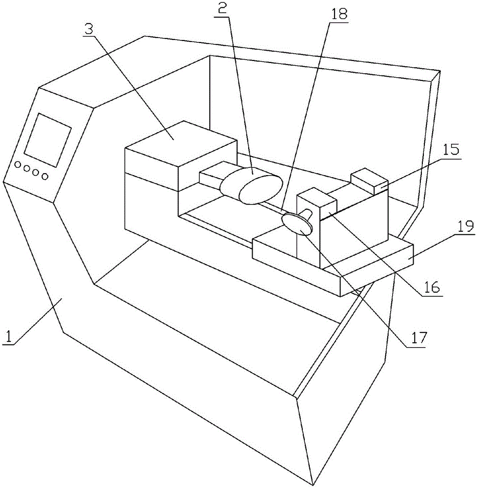
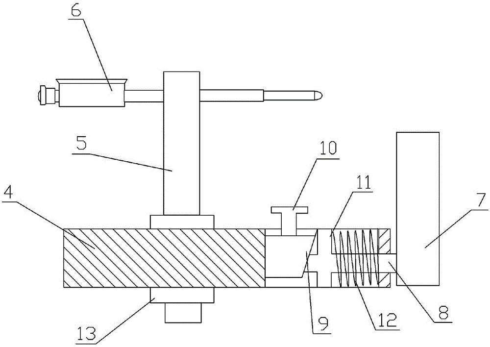
[0012] The reference signs in the drawings of the specification include: lathe main body 1, tool tray 2, fine adjustment mechanism 3, support plate 4, support rod 5, dial indicator 6, fixed plate 7, adjustment rod 8, cone block 9, adjustment bolt 10. The baffle plate 11, the spring 12, the adjusting nut 13, the fixed block 15, the adjusting block 16, the rotating handle 17, the slide rail 18, and the working table 19.

[0013] The embodiment is basically as attached figure 1 Shown: an instrument lathe for processing shift guide shafts, including a lathe body 1 and a tool tray 2 mounted on the lathe body 1. The tool tray 2 is provided with a fine-tuning mechanism 3, and the lathe body 1 is also provided with a fixture for mounting workpieces. The clamp includes a fixed block 15 and an adjusting block 16 arranged oppositely. A clamping hole for the shift guide shaft is formed be...


PUM


Abstract

The invention discloses a meter lathe for shifting guide shaft processing, which comprises a lathe main body and a cutter tray mounted on the lathe main body, wherein a fine adjustment mechanism is arranged on the cutter tray, and comprises a support plate, a support rod, a dial indicator and a fixing plate; the fixing plate is mounted at the end part of the support plate; an inner hole is formed in the end part, where the fixing plate is mounted, of the support plate; an adjustment rod connected with the fixing plate is arranged in the inner hole, and penetrates through the inner hole to be connected with a tapered block; an adjustment bolt is arranged on the tapered block; a baffle is arranged on the adjustment rod positioned in the inner hole; a spring is arranged between one end of the support plate and the baffle; the support rod is fixedly arranged at the other end of the support plate by the adjustment bolt; and the dial indicator is mounted at the upper end of the support rod. The meter lathe for the shifting guide shaft processing is high in precision and efficiency.

Description

Technical field [0001] The invention relates to the technical field of processing automobile parts, in particular to an instrument lathe for processing shift guide shafts. Background technique [0002] Instrument lathes are simple horizontal lathes. Generally speaking, the machining diameter of the largest workpiece is below 250mm. They are usually used to process small workpieces. Due to their high machining accuracy, the machining accuracy of the parts processed on the instrument lathe The requirements are very high. The shift guide shaft is an important part of the transmission and shift system. The processing accuracy of the shift guide shaft is required to be high. It is mainly used to complete the function of shifting, which is of great importance to the safe and reliable driving of the car. Therefore, the shift guide shaft is usually processed on an instrument lathe. However, when processing, the instrument lathe is not a professional processing machine tool for shift guid...

Claims


Application Information

Patent Timeline
IPC IPC(8): B23B5/00B23Q17/22
CPCB23B5/00B23Q17/2233
Inventor 陈明友
Owner CHONGQING YOUBO MACHINERY MFG
Why Eureka
Try Eureka