360 degree rotating lamina rongeur

A rongeur, rotating technology, applied in the field of surgical forceps, can solve the problems of inconvenient use, inconvenient operation, and jaw offset of the lamina rongeur, achieve stable sliding connection, improve use stability, The effect of increasing accuracy

Active Publication Date: 2017-03-22
江苏百易得医疗科技有限公司
View PDF9 Cites 0 Cited by
  • Summary
  • Abstract
  • Description
  • Claims
  • Application Information

AI Technical Summary

Problems solved by technology

It can be seen that the above lamina rongeur has the following disadvantages: the above lamina rongeur does not have any arrangement to rotate the static pliers stem and / or the dynamic pliers rod to a certain angle, resulting in a gap between the static pliers stem and the dynamic pliers rod. The opening direction of the jaws is fixed, so if the operator wants to change the direction of the jaws, he can only rotate the arm to rotate the position of the entire lamina rongeur, so as to achieve the purpose of changing the direction of the jaws. In this case, the surgeon needs Often change the position of the arm, causing inconvenient operation and affecting the operator
[0003] In order to change the problem of inconvenient use of the lamina rongeur in the above technology, Chinese patent document CN103284783A discloses a universal lamina rongeur, which includes three parts, the upper jaw, the lower jaw and the handle. The mechanism consisting of the plate body, the tail of the upper jaw, the body of the lower jaw, the rotating armrest, the front handle, the rear handle, the sliding push rod, the fixing seat and the shell, the rongeur can rotate in the direction of the handle by rotating the rotating armrest. Under the same condition, to change the opening direction of the rongeur jaw, through the movement between the front handle and the rear handle, push the upper jaw to move relative to the lower jaw, so as to close the jaw and bite off the bone tissue
[0004] In the above technique, a rotating armrest is provided on the lamina rongeur, and when the direction of the handle remains unchanged, the rotating armrest is turned to change the opening direction of the rongeur jaw; however, when the sliding push rod pushes the tail of the upper jaw When the part is in the middle, because there is a space or gap between the sliding push rod and the surgical inner wall, the position of the sliding push rod will move when the sliding push rod pushes the upper jaw to slide back and forth, thus causing the upper jaw to move. The phenomenon that the jaws formed by the lower jaw deviate from the lower jaw during use

Method used


Image

  • 360 degree rotating lamina rongeur
  • 360 degree rotating lamina rongeur
  • 360 degree rotating lamina rongeur

Examples


Embodiment 1

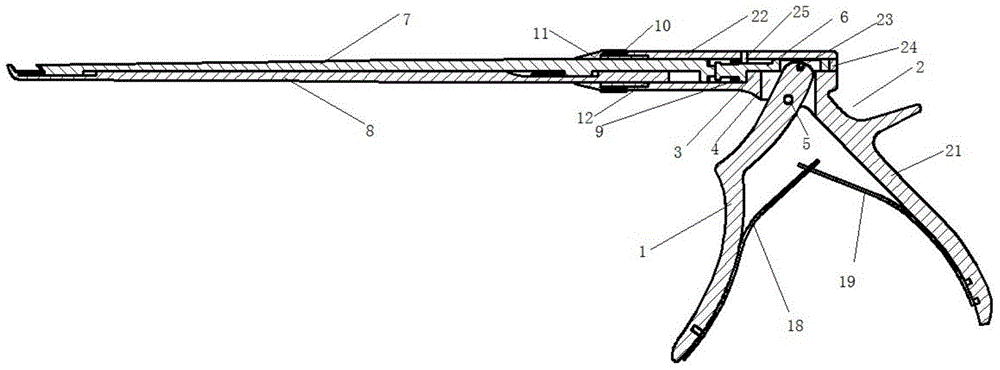
[0045] Such as Figure 1-9 As shown, this embodiment provides a 360-degree rotating lamina rongeur, including a front pliers foot 1 , a rear pliers foot 2 , a push rod 6 , a cover plate 7 , a bottom plate 8 , a rotating structure, and a limit pin 25 .

[0046] The front pliers foot 1 has a shape and structure for finger gripping, which is convenient for fingers gripping.

[0047] The rear pliers foot 2 includes a palm joint 21 and a pliers body 22 connected together; the palm joint 21 has the shape and structure of a palm joint, and is connected with the front pincers foot in a finger grip shape. 1, used together to perform gripping and loosening actions; the pliers body 22 has an inner cavity, the structure of which is not unique, and the size of the inner cavity may be different at different positions of the pliers body 22, and may be To pass through the through hole of the pliers body 22, preferably, the inner cavity of the pliers body 22 is a through hole with a circular ...

Embodiment 2

[0056] This embodiment provides a 360-degree rotating lamina rongeur, which is a modification on Embodiment 1, and the modification is as follows:

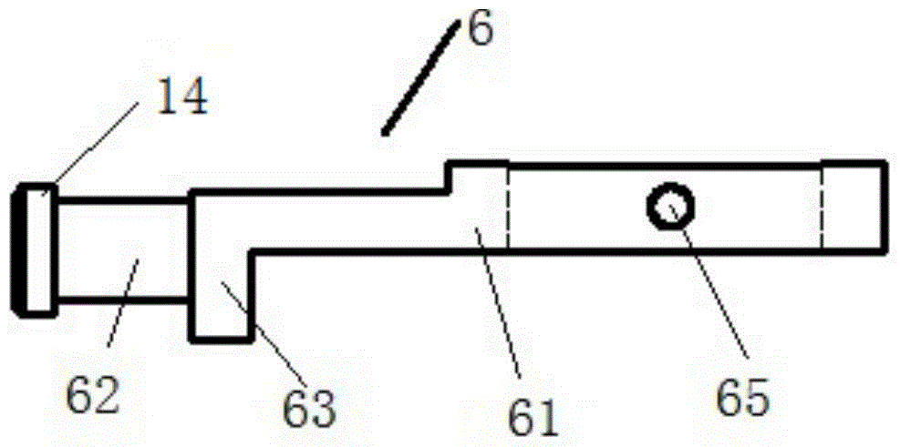
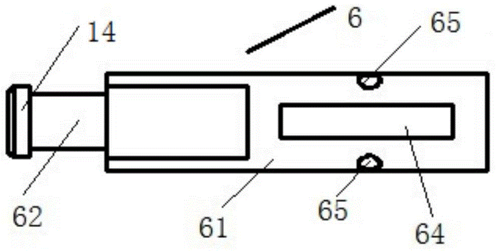
[0057] The rod head of the push rod is cylindrical and is provided with a circular inner cavity, and the inner diameter of the circular inner cavity near the connecting part is larger than the inner diameter of the circular inner cavity at the end of the rod head; The rear part of the cover plate is cylindrical, and a protrusion is arranged at the tail end of the rear part of the cover plate; the protrusion is arranged in cooperation with the circular inner cavity close to the connecting part.

[0058] The bottom plate is provided with a T-shaped protrusion, and a T-shaped groove matching the T-shaped protrusion is arranged on the cover plate, and a T-shaped groove suitable for the T-shaped groove is provided at the T-shaped groove. The type protrusion enters the installation port of the T-shaped groove.

[0059] Simply put, the ...


PUM


Abstract

The invention relates to a 360-degree rotary type vertebral plate bone rongeur. A stop pin is arranged on the inner cavity wall of a rongeur body, and the lower end of the stop pin is integrated closely with the upper surface of a push part of a push rod. By arranging the stop pin, the lower end of the stop pin and the upper surface of a bearing platform limit the push part of the push rod, so that while the forward and backward movement of the push rod is not influenced, the push rod is prevented from position deviation during forward and backward movement due to a space existing between the push part of the push rod and the inner cavity wall of the rongeur body, and then cannot cause a phenomenon of deviation of a cutting edge formed by a cover plate and base plate; and furthermore, the stop pin is arranged right above the left end side of the bearing platform, so that the deviation force borne by the lower end of the stop pin is minimum, abrasion is reduced to the utmost extent, the lower end of the stop pin and the upper surface of the bearing platform can fix and limit the push part, and the service life of the stop pin can be prolonged.

Description

technical field [0001] The invention relates to a 360-degree rotating lamina rongeur, which belongs to the field of surgical forceps in surgical instruments. Background technique [0002] In neurosurgery or spinal surgery, a lamina rongeur is usually required to bite the skull or vertebrae. The same kind of rongeur in the prior art is composed of a pliers rod device, a pliers main body device and a pliers handle. The device is composed of a pliers rod device inserted in the pliers main body device. The pliers handle device includes a large handle and a small handle connected to each other. The pliers rod device is provided with a static pliers rod, a moving pliers rod, a push rod and a push rod compression spring. , The static and dynamic tong rods match each other, the push rod is connected with the dynamic tong rod through threads, and the push rod compression spring is installed between the static tong stalk and the push rod. It can be seen that the above lamina rongeur ...

Claims


Application Information

Patent Timeline
Patent Type & Authority Patents(China)
IPC IPC(8): A61B17/56A61B17/28
CPCA61B17/2812A61B17/2841A61B2017/564
Inventor 丁建忠
Owner 江苏百易得医疗科技有限公司
Why Eureka
Try Eureka