Adjustable shoe material rack

An adjustable and shoe-material technology, applied to footwear, shoe-making machinery, clothing, etc., can solve the problems of lower shoe-making efficiency, limited load-bearing area, and increased number of pallet layers, so as to improve shoe-making efficiency and reduce production cost effect

Inactive Publication Date: 2015-11-18
SUZHOU QISHUO INFORMATION TECH CO LTD
View PDF8 Cites 2 Cited by
  • Summary
  • Abstract
  • Description
  • Claims
  • Application Information

AI Technical Summary

Problems solved by technology

The above-mentioned shoe racks generally include brackets and multi-layer trays. When in use, shoemaking materials such as shoe lasts, soles, and uppers are placed on the trays. However, the bearing surface of each layer of trays is fixed, and the bearing area is limited. Placing shoemaking materials on the bearing surface cannot effectively use the space it occupies, so more shoe racks are needed, which wastes resources and takes up a lot of space, reducing production efficiency
In addition, the area for placing shoe materials on each layer of trays is limited, resulting in an increase in the number of layers of trays on the brackets. The distance between the upper and lower trays in the prior art cannot be adjusted, resulting in that the trays cannot flexibly place shoe materials of different heights. When taking shoe materials, it will be affected by the pallets of adjacent layers, resulting in a decrease in shoemaking efficiency

Method used


Image

  • Adjustable shoe material rack
  • Adjustable shoe material rack
  • Adjustable shoe material rack

Examples


Embodiment Construction

[0021] The specific implementation manners of the present invention will be further described in detail below in conjunction with the accompanying drawings and embodiments. The following examples are used to illustrate the present invention, but are not intended to limit the scope of the present invention.

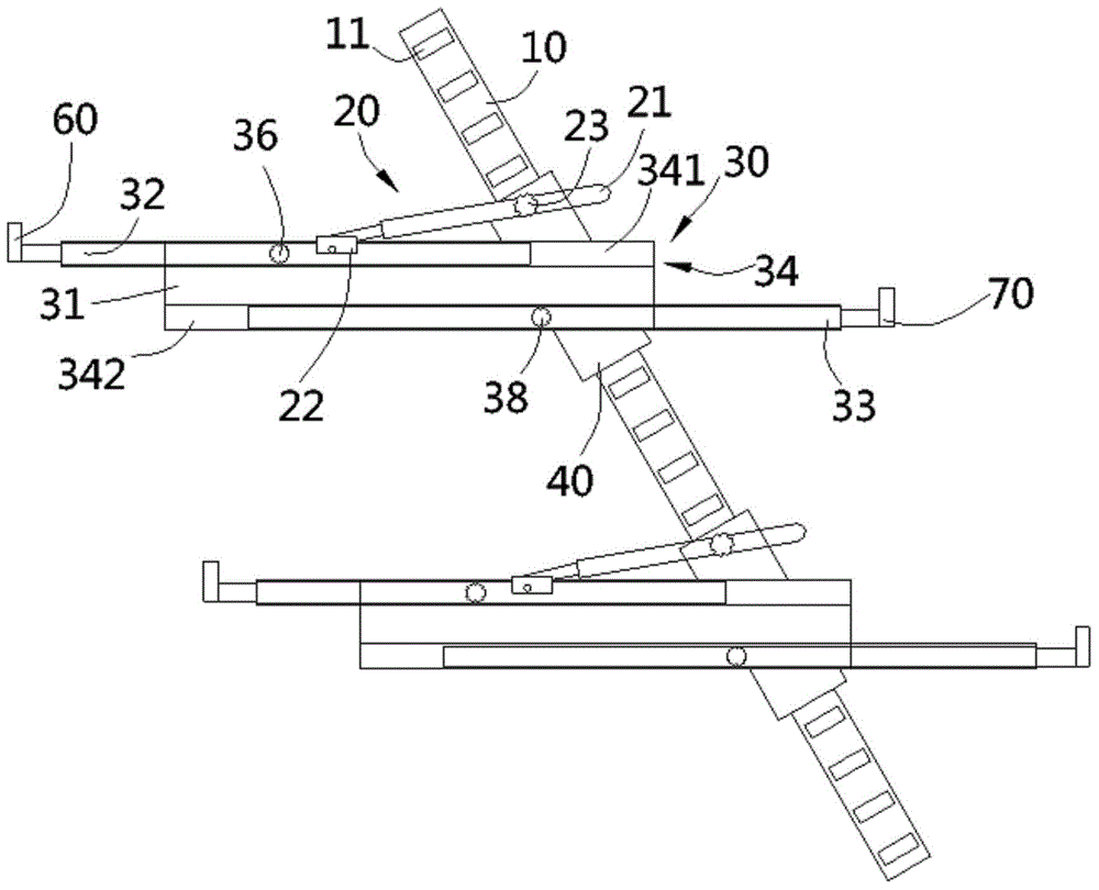
[0022] see figure 1 , a kind of adjustable shoe material placement shoe rack according to the present invention, comprises two inclined supporting columns 10, several groups of tray brackets 20 fixed on the said supporting columns and fixed on each group of tray brackets Several pallets 30 fixed on the support column 10;

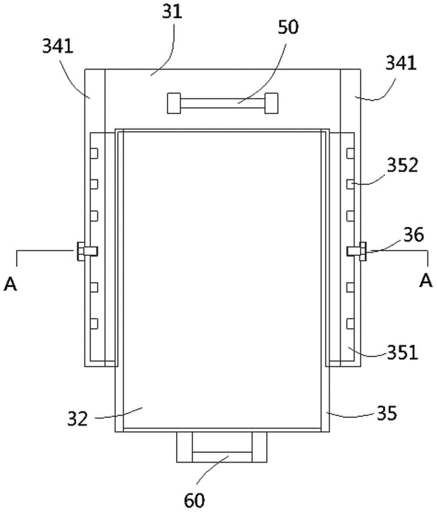
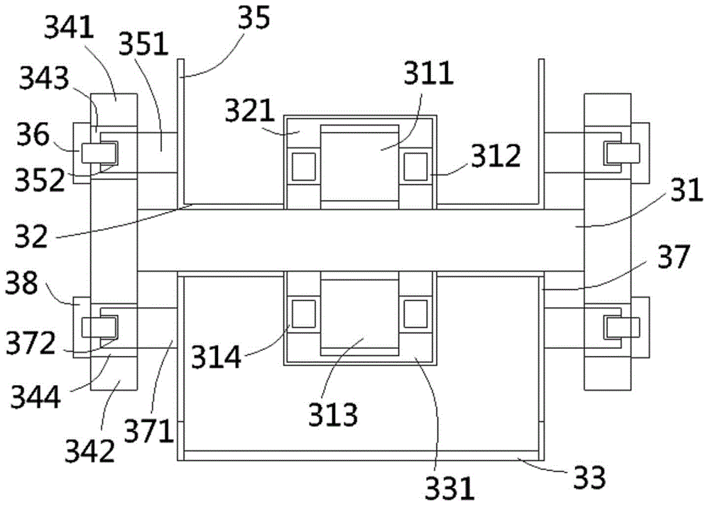
[0023] see Figure 1 to Figure 3 , the tray 30 includes a base plate 31, an upper adjustment plate 32 arranged above one side of the base plate and a lower adjustment plate 33 arranged under the other side of the base plate, and two surrounding plates are formed on the left and right sides of the base plate 31 34. The upper and lower end surfaces of t...


PUM


Abstract

The invention discloses an adjustable shoe material rack. The adjustable shoe material rack comprises two supporting pillars, a plurality of groups of tray supports fixed to the supporting pillars, and a plurality of trays fixed to the tray supports. Each tray comprises a base plate and an upper adjusting plate arranged above one side of the base plate, wherein an upper surrounding plate is formed on the left side and right side of the base plate, two upper guiding plates are formed on the left side and right side of the upper adjusting plate, a plurality of upper screw holes are evenly formed in the outer wall of each upper guiding plate and arranged in a linear mode, and upper bolts are in screw joint with the upper screw holes; oblique sleeves are fixedly inserted into the two sides of the rear end of the base plate, and the supporting pillars are sleeved with the sleeves. A plurality of cutting grooves are evenly formed in each supporting pillar in the axial direction and arranged in a linear mode. Each tray support comprises a supporting rod and a fixed block, wherein an adjusting bolt penetrates through the supporting rod to be connected to the corresponding sleeve in a screwed mode, the tail end of the adjusting bolt is inserted in the corresponding cutting groove, and the fixed block is fixed to the corresponding upper surrounding plate. According to the adjustable shoe material rack, the distance between different layers of trays can be adjusted, and the bearing areas of the trays can be freely increased.

Description

Technical field: [0001] The invention relates to the technical field of shoe racks for shoemaking, in particular to an adjustable shoe rack for placing shoe materials. Background technique: [0002] At present, in the shoe-making industry, due to the relatively strict specification requirements for shoes, special-purpose shoe-making shoe racks are generally used to transport shoe-making materials such as shoe lasts, soles, and uppers, and the shoe lasts, soles, and uppers are paired and placed in corresponding positions. . The above-mentioned shoe racks generally include brackets and multi-layer trays. When in use, shoemaking materials such as shoe lasts, soles, and uppers are placed on the trays. However, the bearing surface of each layer of trays is fixed, and the bearing area is limited. The space occupied by shoe-making materials placed on the bearing surface cannot be effectively used, so more shoe racks are required, which wastes resources and takes up a large space, ...

Claims


Application Information

Patent Timeline
IPC IPC(8): A43D117/00
Inventor 钱彩华
Owner SUZHOU QISHUO INFORMATION TECH CO LTD
Why Eureka
Try Eureka