
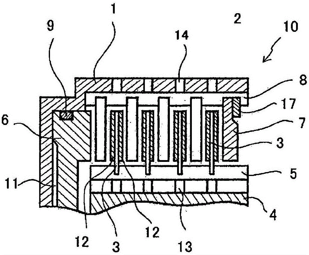
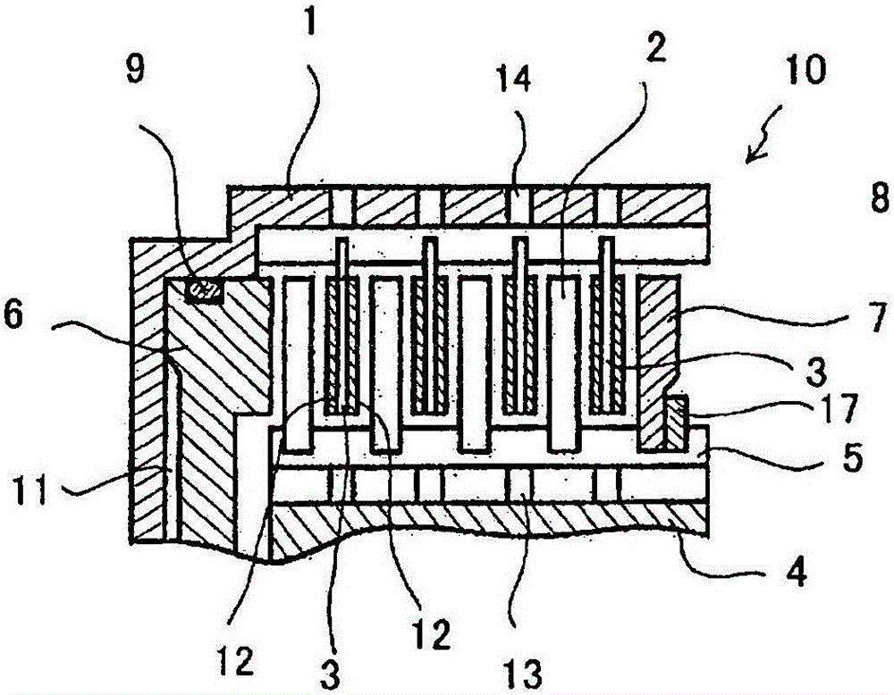
Friction plate and wet multi-plate clutch provided with friction plate

一种摩擦片、离合器的技术,应用在湿式多片离合器领域,能够解决拖曳转矩变大、拖曳转矩大、不容易排出等问题,达到提高冷却效率、降低效果好、降低拖曳转矩的效果

Active Publication Date: 2015-11-11
NSK WARNER
View PDF12 Cites 7 Cited by
  • Summary
  • Abstract
  • Description
  • Claims
  • Application Information

AI Technical Summary

Problems solved by technology

[0005] However, in recent years, in order to improve shift responsiveness for the purpose of improving power performance while improving fuel efficiency, there is a tendency that the gap between the friction plate and the separator is smaller than before, and that the gap between the friction plate and the separator tends to be smaller during idling. The drag torque generated by the oil film in the middle becomes larger
[0006] In addition, the oil supplied to the oil passage penetrating from the inner diameter side to the outer diameter side is sucked into the friction material due to the rotation, and once the sucked oil enters between the friction plate and the separator, it is not easy to be discharged. Especially in the area where the gap between the plate and the separator is small and the rotational speed is low, the drag torque generated by the viscosity between the friction material and the corresponding separator is large

Method used


Image

  • Friction plate and wet multi-plate clutch provided with friction plate
  • Friction plate and wet multi-plate clutch provided with friction plate
  • Friction plate and wet multi-plate clutch provided with friction plate

Examples


no. 1 example

[0054] image 3 It is a partial front view of the friction plate 3 showing the first embodiment of the present invention. The friction sheet 3 has a friction surface 25 formed by attaching a plurality of friction material segments 21 arranged substantially equally in the circumferential direction with an adhesive or the like on a substantially annular core plate 20 . The core plate 20 has splines 20 a engaged with the splines 5 of the bushing 4 on the inner periphery.

[0055] Such as image 3 As shown, one friction material segment 21 is provided with an oil groove 23 having an opening 23a opening in the direction of the outer periphery 27 of the friction plate 3 and a closed end 23b terminating between the inner and outer periphery. One oil groove 23 not penetrating in the inner diameter direction is provided on the friction material segment 21 .

[0056] A gap having a predetermined circumferential width is provided between adjacent friction material segments 21 . At th...

no. 2 example

[0064] Figure 4 It is a partial front view of the friction plate 3 showing the second embodiment of the present invention. In the second embodiment, the shapes of the friction material segments attached and fixed on the core plate 20 are different. In the second embodiment, friction material segments of two shapes are fixed to the core plate 20 as in the first embodiment. The friction material segment 31 has an opening 33 a that opens toward the outer peripheral edge of the friction sheet 3 , and a closed end 33 b that ends between the inner and outer peripheral edges. The radial length of the oil groove 33 is 1 / 2 or more of the radial width of the friction material segment 31 . Therefore, the end portion 33b of the oil groove 33 exceeds half of the width in the radial direction and is located at a position deviated to the radially inner side.

[0065] From Figure 4 It can be seen that the oil groove 33 is arranged to deviate from one end 35 of the friction surface 25 of t...

no. 3 example

[0081] Figure 5 It is a partial front view of a friction plate showing a third embodiment of the present invention. The third embodiment is a modified example of the second embodiment. The structures of the friction material segment 31 and the friction material segment 32 are the same as those of the second embodiment. In the third embodiment, between a pair of friction material segments composed of adjacent friction material segments 31 and 32 , a friction material block 50 not provided with an oil groove is disposed.

[0082] Such as Figure 5 As shown, the friction material block 50 is not formed with the oil grooves opening in the outer peripheral direction that the friction material segments of the first embodiment and the second embodiment have. The friction material block 50 has a shape in which the width in the circumferential direction becomes smaller from the outer diameter portion 50a toward the inner diameter portion 50b. Therefore, if the friction material bl...


PUM


Abstract

Provided are: a friction plate that takes in large quantities of air into a lubricating oil at the friction surface and reduces the shear resistance of the lubricating oil interposed between friction members, thereby greatly reducing the drag torque during idling compared to what has been conventional; and a wet multi-plate clutch provided with the friction plate. At the friction plate, a plurality of friction element segments are affixed in a ring shape on a ring-shaped core plate, and the friction plate has friction element segments provided with an oil groove having an end that terminates between an inner and outer peripheral edge and an opening that opens in the outer peripheral edge direction of the friction plate, an oil pathway that interconnects in the inner-outer peripheral edge direction of the friction plate is provided between the friction element segments, and the oil pathway at least at one section has a first shape having a width in the peripheral direction that becomes narrower from the inner peripheral edge of the friction plate towards the outer peripheral edge.

Description

technical field [0001] The present invention relates to a friction plate used for a clutch or brake of an automatic transmission of a vehicle, and a wet multi-plate clutch including the friction plate. More specifically, it relates to improvement of an oil passage formed in a friction surface of a friction plate. Background technique [0002] Generally, in a wet multi-disc clutch, friction plates and spacers are alternately arranged between a hub and a bush of a clutch or brake, and the clutch is engaged and disengaged by pressing and disengaging a clutch piston. [0003] In addition, in recent years, the demand for low fuel consumption of automobiles has been increasing. In automatic transmissions, in order to reduce the power loss when the clutch is not engaged, it is also required to reduce the drag torque between the friction plate and the separator. . [0004] In general, wet multi-disc clutches used in automatic transmissions (ATs) often have a structure in which lub...

Claims


Application Information

Patent Timeline
Patent Type & Authority Applications(China)
IPC IPC(8): F16D13/62F16D25/0638F16D25/064F16D69/00
CPCF16D25/0638F16D13/52F16D13/648F16D13/72F16D13/74F16D25/123F16D69/00F16D2069/004F16D2300/0214F16D2121/02
Inventor 高林秀明池田洋介冈田正宪小林昌弘田中修村松史昌渡边佳则山田真弘河合勉藤田和幸
Owner NSK WARNER
Learn More