
Data transmission method of network disaster-tolerant system

A data transmission method and network technology, which is applied in the field of data disaster recovery, can solve the problems of increasing the data transmission volume of the active and standby nodes, increasing the service duration of the main node, and the unavailability of standby data disaster recovery data, so as to reduce the cost of full-disk replication Probability, data integrity performance guarantee, effect of reducing data transmission volume

Active Publication Date: 2015-11-11
深圳市傲冠软件股份有限公司
View PDF7 Cites 15 Cited by
  • Summary
  • Abstract
  • Description
  • Claims
  • Application Information

AI Technical Summary

Problems solved by technology

In the prior art, when re-shaking hands between nodes, especially in the case of unplanned migration, the full-disk copy mode is generally adopted, which undoubtedly increases the service duration of the master node and increases the communication between the master and backup nodes. The amount of data transmission greatly prolongs the time required for application recovery and increases the time for incomplete backup machine data, because incomplete backup machine data is likely to cause the risk of unavailable disaster recovery data
[0012] In addition, the following defects also exist in the prior art: during incremental replication (incremental replication is implemented based on bitmap), if the host receives external newly written data every time, it will immediately generate a new bitmap, which will As a result, the incremental synchronization has been carried out and the moment when the bitmap is 0 cannot be obtained, resulting in the incomplete state of the standby machine data

Method used


Image

  • Data transmission method of network disaster-tolerant system
  • Data transmission method of network disaster-tolerant system

Examples


Embodiment Construction

[0048] In order to have a clearer understanding of the technical features, purposes and effects of the present invention, the specific implementation manners of the present invention will now be described in detail with reference to the accompanying drawings.

[0049] The disaster recovery system includes at least two nodes. Generally, the source node that can be replicated is called the primary node (also called the primary node), and the replicated destination node (one or more) is called the standby node (also called the secondary node). . Usually, the disk device on the master node is readable and writable, but the disk device on the standby node cannot be accessed until the standby node becomes the master node. The switching of active and standby roles of nodes is usually automatically realized by the corresponding cluster software, which will not be described here.

[0050] In the present invention, each node stores metadata information related to data transmission with...


PUM


Abstract

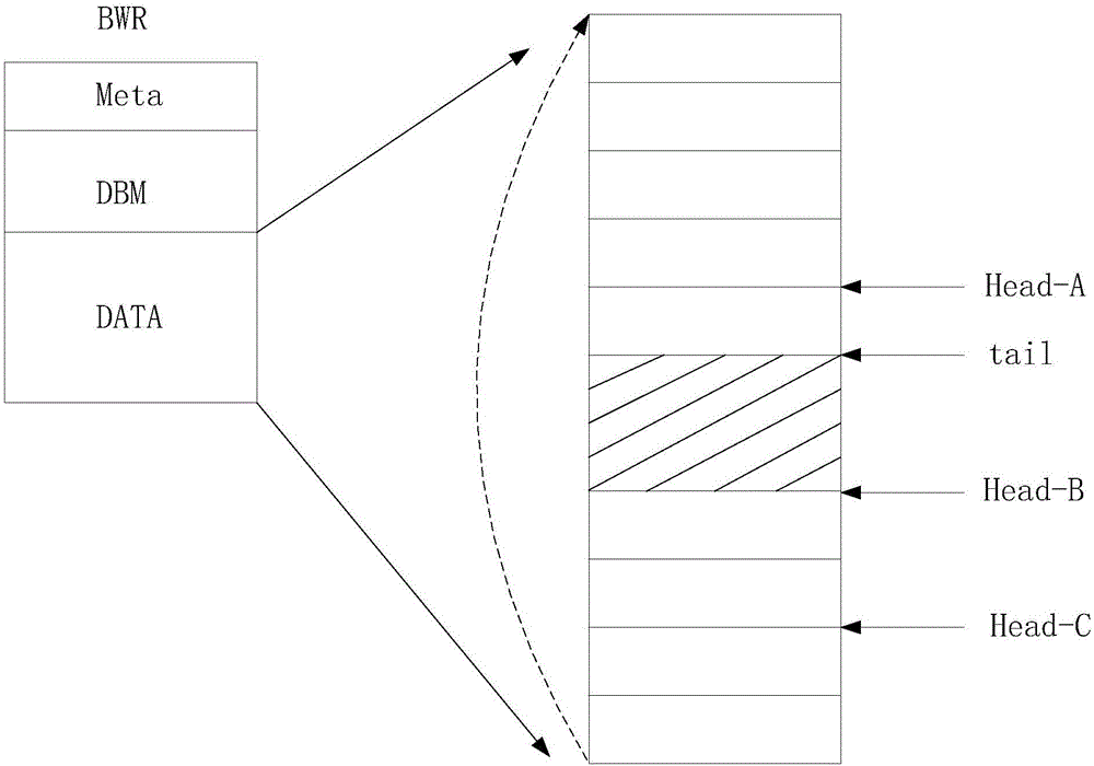
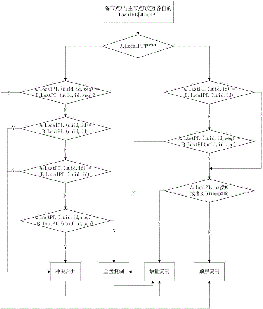
The invention relates to a data transmission method of a network disaster-tolerant system. The system comprises a master node and at least one spare node; meta data information is stored in each node; the meta data information comprises information of the master node related to output transmission of the node in the last time and information of data written in the previous time; and the method comprises the following steps that: S1, the spare node and the master node are connected to shake hands and exchange respective meta data information; and S2, the master node compares the self meta data information with the meta data information of the spare node and determines one of four replication modes so as to realize data transmission. According to the invention, which mode is adopted is automatically judged while shaking hands again; the time required by disaster-tolerant recovery is shortened; furthermore, if the master node writes in data while incremental synchronization is carried out, a data incremental bitmap is not updated immediately; but, after incremental replication in this round is finished, incremental synchronization is carried out again after data between a head pointer of the spare node and a head pointer of the master node is converted into the data incremental bitmap; and therefore, the data integrity of the spare node is ensured.

Description

technical field [0001] The invention relates to the technical field of data disaster recovery, in particular to a data transmission method of a network disaster recovery system. Background technique [0002] With the development of Internet applications, the number of Internet users is getting wider and wider, and a large amount of user data is stored on Internet servers, all of which put forward stricter requirements for the availability of applications running on the Internet and the reliability of data storage. requirements, because an application failure may cause immeasurable losses, and data loss will have fatal consequences. [0003] For example, on the morning of April 21, 2011, Amazon's EC2 and RDS services experienced network delays and connection errors, resulting in intermittent inaccessibility to websites such as Foursquare, Quora, and RedditPaper.li. There are many large-scale websites placed on EC2. Some foreign media said that half of the US Internet was aff...

Claims


Application Information

Patent Timeline
IPC IPC(8): H04L12/24H04L1/22
CPCH04L1/22H04L41/0654
Inventor 李俊
Owner 深圳市傲冠软件股份有限公司
Learn More