
Optical signal time-space conversion device and method

A space-time conversion and optical signal technology, applied in signal transmission systems, non-electrical signal transmission systems, instruments, etc., can solve the problems of complex processing technology and low precision, achieve high precision, large data volume, high parallelism and The effect of large capacity

Active Publication Date: 2018-10-23
SHANGHAI JIAODA INTELLECTUAL PORPERTY MANAGEMENT CO LTD
View PDF5 Cites 0 Cited by
  • Summary
  • Abstract
  • Description
  • Claims
  • Application Information

AI Technical Summary

Problems solved by technology

However, when the number of fiber taps is large, it will lead to problems such as low conversion accuracy and complicated processing technology.

Method used


Image

  • Optical signal time-space conversion device and method
  • Optical signal time-space conversion device and method
  • Optical signal time-space conversion device and method

Examples


Embodiment Construction

[0027] The present invention will be described in detail below in conjunction with specific embodiments. The following examples will help those skilled in the art to further understand the present invention, but do not limit the present invention in any form. It should be noted that those skilled in the art can make several modifications and improvements without departing from the concept of the present invention. These all belong to the protection scope of the present invention.

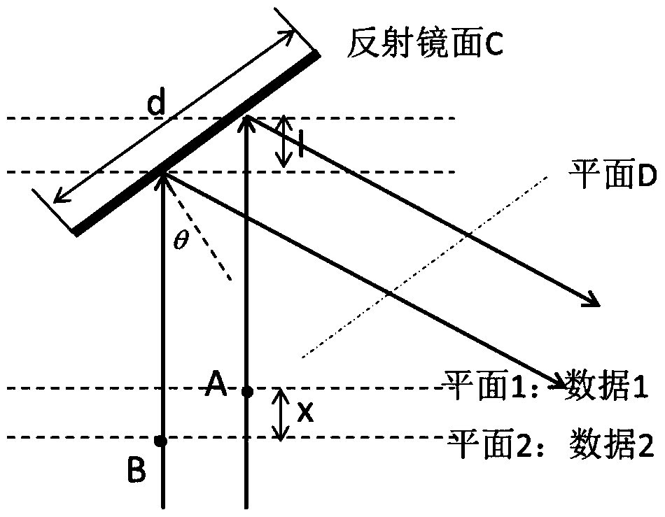
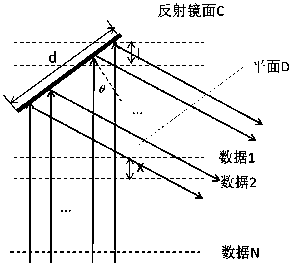
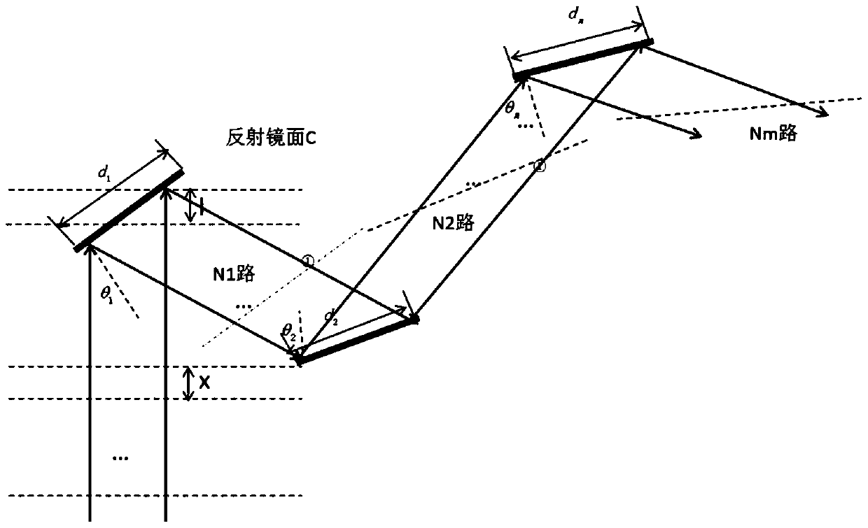
[0028] The device and method provided by the present invention introduce the optical path difference through the inclination angle between the reflector and the incident wave beam, and use the optical path difference to realize the time-space conversion of the optical signal.

[0029] The specific embodiment of the serial-to-parallel conversion technology of the optical signal based on the reflector system of the present invention is as follows:

[0030] (1) Preparation of optical devices: Prepare...


PUM


Abstract

The invention discloses an optical signal time-to-space conversion device and method. The device comprises several same reflectors with diameters of d, a laser source system for producing parallel light, a spatial light modulator and a light splitting prism. According to the number of light paths needing to be output in parallel, a reflector system composed of the several reflectors is designed and a light path is built and debugged. The parallel light produced by the laser source system goes through the light splitting prism, then irradiates the spatial light modulator loaded with serially-transmitted data, and is modulated by the spatial light modulator so that the parallel light is loaded with the serial data. The parallel light reflected by the spatial light modulator goes through the light splitting prism again and then goes into the reflector system and the parallel light going through the reflector system is in a parallel data transmission mode.

Description

technical field [0001] The invention relates to a time-space conversion of optical signal transmission, in particular to a brand-new method for realizing the time-space conversion of optical signals by using a mirror system. Background technique [0002] Optical information processing is a new subject developed in recent years. The subject develops rapidly and has become an important branch of information science. Compared with other forms of information processing technology, the advantages of optical information processing lie in its high degree of parallelism and large capacity. Generally, the input optical signal for optical information processing is converted from an electrical signal. Usually, the data transmission mode of the electrical signal is serial, and the input optical signal thus converted is also serial. In order to achieve a high degree of parallelism in optical information processing, it is meaningful and crucial to perform serial-to-parallel conversion of...

Claims


Application Information

Patent Timeline
Patent Type & Authority Patents(China)
IPC IPC(8): G08C23/04
Inventor 刘磊王开志刘兴钊
Owner SHANGHAI JIAODA INTELLECTUAL PORPERTY MANAGEMENT CO LTD
Learn More