
Differential current measuring module

A technology for measuring components and differential currents, applied to electrical components, measuring devices, measuring electrical variables, etc., can solve problems such as expensive and unfavorable differential current measuring equipment

Inactive Publication Date: 2015-11-11
BENDER SA
View PDF0 Cites 10 Cited by
  • Summary
  • Abstract
  • Description
  • Claims
  • Application Information

AI Technical Summary

Problems solved by technology

[0006] The use of known differential current measuring devices has proven to be disadvantageous due to their structurally complex integration into electrical installations, for example into charging installations with integrated control and protection devices , because the primary conductor has to be guided through the current transformer in the often confined installation space and has to be routed by complex and expensive manual means on the printed mounting board

Method used


Image

  • Differential current measuring module
  • Differential current measuring module
  • Differential current measuring module

Examples


Embodiment Construction

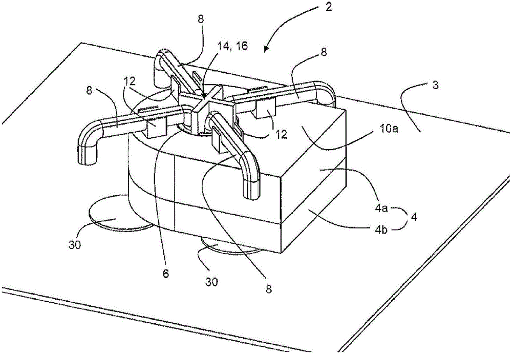
[0048] figure 1 An external view of a differential current measuring assembly 2 according to the invention is shown, which is mounted on a printed mounting board 3 . The differential current measurement assembly 2 is an integrated assembly for differential current measurement which can be equipped with a printed mounting board 3 .

[0049] In the embodiment example shown, the differential current measurement assembly 2 consists of a split housing 4 with an upper housing part 4a and a lower housing part 4b. The housing 4 has a cylindrical conduit 6 in which four primary conductors 8 are arranged as part of the differential current measuring assembly 2 .

[0050] The four primary conductors 8 thus form a line section through which the feeder to be monitored with three phase conductors (L1, L2, L3) and a neutral conductor (N) runs in the conduit 6 for registering differential currents .

[0051] Furthermore, in single-phase or two-phase power supply systems with high current l...


PUM


Abstract

A differential current measuring module is composed of a housing that encases a current transformer core and a printed circuit board, the current transformer core surrounding a line duct of the housing and having at least one secondary winding. The differential current measuring module is characterized in that in the line duct, at least one primary conductor is led out on a top side of the housing to be connected to an external electrical feed line and whose other end protrudes out of a bottom side of the housing and is provided with a solder terminal. The principle idea is based on continuing the electrical line to be monitored, in sections, as a primary conductor in the effective area of the current transformer core so as to advantageously arrive at a differential current measuring device whose integration is constructionally simple and which offers an uncomplicated connecting option.

Description

technical field [0001] The invention relates to a differential current measuring assembly consisting of a housing surrounding a current transformer core which surrounds a wire tube of the housing and a printed circuit board and which has at least one secondary winding. Background technique [0002] Measuring devices such as residual current monitoring devices (RCM) or residual current protective devices (RCD) are well known for monitoring and protection purposes of electrical installations. [0003] The known method and device are mainly based on the principle of galvanic isolation current measurement, in which all active conductors on the power line to be monitored are conducted as primary windings (primary conductors) of measuring current transformers with A toroidal current transformer core made of ferromagnetic material and having at least one secondary winding. A current transformer core is usually incorporated into a housing with a conduit for the feeder to be monitor...

Claims


Application Information

Patent Timeline
Patent Type & Authority Applications(China)
IPC IPC(8): G01R19/00
CPCG01R15/18G01R15/207G01R15/22G01R17/00H01F38/30H01F27/2828H01F27/306H01F2038/305G01R15/185G01R19/10
Inventor 温弗雷·摩尔迈克尔·卡默迈克尔·普林茨-韦内尔
Owner BENDER SA
Learn More