A composite glass door body structure

A composite and glass technology, applied in the direction of all-glass wing fans, etc., can solve problems such as affecting re-installation, failure to connect, troublesome installation, etc., and achieve the effect of fixing firmly and ensuring the closing effect

Active Publication Date: 2017-01-11
南陵县建设投资有限责任公司
View PDF6 Cites 0 Cited by
  • Summary
  • Abstract
  • Description
  • Claims
  • Application Information

AI Technical Summary

Problems solved by technology

[0004] The existing door body is installed in the door frame, which generally needs to be connected by a hinge between the door body and the door frame, which is not only troublesome to install, but also makes the connection side between the door body and the door frame uneven, affecting the overall appearance And when the door body is disassembled, there is a bolt connection hole in the place where the hinge is disassembled. Since the door body is generally a wooden door body, it cannot be connected in the original bolt connection hole when it is installed again. installation, and affect the aesthetics
[0005] At the same time, the existing glass doors generally use a fixed connection frame on one side of the glass door, which is connected to the door frame through the connection frame. When the glass door is closed, there is no fixing device between the other side and the door frame. It is set on the vertical rotating shaft provided in the connecting frame, and the position when the glass door is closed is realized by the limit part provided on the vertical rotating shaft. When the outside wind is relatively strong or people only need to push the glass door lightly, The glass door can be opened at a certain angle, so that the closing effect is not ideal when closing the door, and the effect is limited

Method used


Image

  • A composite glass door body structure
  • A composite glass door body structure

Examples


Embodiment Construction

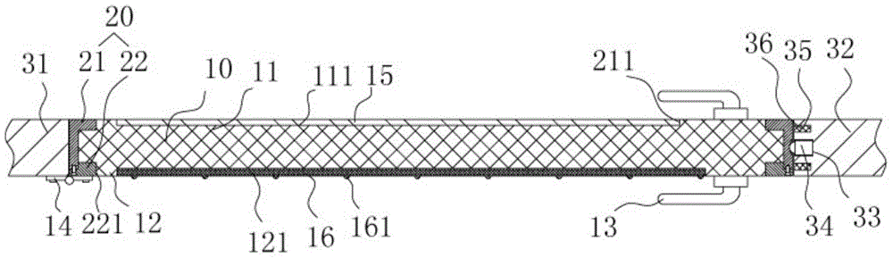
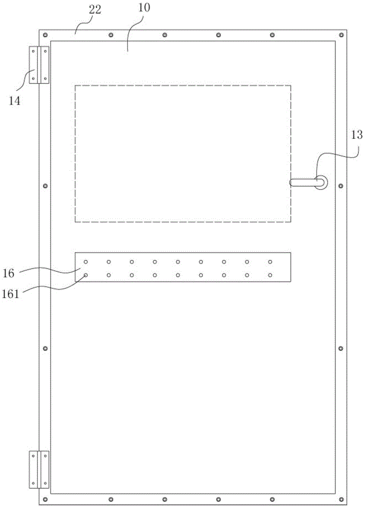
[0019] Example: see Figures 1 to 2 As shown, a composite glass door structure includes a glass door panel 10 and a frame 20, the frame 20 includes a front frame body 21 and a rear frame panel 22, the front frame body 21 has a rectangular through groove 211 on the plate surface, and the glass The door panel 10 is inserted into the front frame body 21, the raised portion 11 on the front wall of the glass door panel 10 is inserted into the rectangular through groove 211, the back of the glass door panel 10 is pressed against the rear frame panel 22, and the rear frame panel 22 passes through Bolts are fixedly connected to the front frame body 21, and the rear raised portion 12 provided on the rear wall of the glass door panel 10 is inserted into the rear rectangular channel 221 provided in the middle of the rear frame panel 22, and the glass door panel 10 is clamped on the front frame body. 21 and the rear frame plate 22, a door handle 13 is fixed on the glass door plate 10, and...


PUM


Abstract

The invention discloses a combined type glass door body structure which comprises a glass door board and a frame. The frame comprises a front frame body and a rear frame body. A rectangular through groove is formed in the board of the front frame body. The glass door board is inserted into the front frame body in a sleeved mode. A protruding portion arranged on the front wall face of the glass door board is inserted into the rectangular through groove in a sleeved mode. A rear frame board abuts against the back face of the glass door board in a pressed mode. The rear frame board is fixedly connected to the front frame body through a bolt. A rear protruding portion arranged on the rear wall face of the glass door board is inserted into a rear rectangular through groove in the middle of the rear frame board in a sleeved mode. The inner side wall of the right side frame body of the door frame is provided with a threaded hole. A ball bulb plunger is in screw connection with the threaded hole. A steel ball of the ball bulb plunger stretches out of the threaded hole and is embedded into a concave hole in the right side edge of the front frame body. The glass door board is fixed into the frame and hinged into the door frame through the frame, and the closing position of the glass door is firmly fixed through the ball bulb plunger, and the closing effect of the glass door body is further ensured through a permanent magnet strip.

Description

[0001] Technical field: [0002] The invention relates to the technical field of door and window equipment, and more specifically relates to a composite glass door body structure. [0003] Background technique: [0004] The existing door body is installed in the door frame, which generally needs to be connected by a hinge between the door body and the door frame, which is not only troublesome to install, but also makes the connection side between the door body and the door frame uneven, affecting the overall appearance And when the door body is disassembled, there is a bolt connection hole in the place where the hinge is disassembled. Since the door body is generally a wooden door body, it cannot be connected in the original bolt connection hole when it is installed again. Installation, but also affect the aesthetics. [0005] At the same time, the existing glass doors generally use a fixed connection frame on one side of the glass door, which is connected to the door frame th...

Claims


Application Information

Patent Timeline
Patent Type & Authority Patents(China)
IPC IPC(8): E06B3/02
Inventor 傅华月
Owner 南陵县建设投资有限责任公司
Why Eureka
Try Eureka