Clay Shredder

A shredder and clay technology, which is applied in the field of clay shredders, can solve the problems of scrapping, burning of motor coils, and widening of the width of the shaft head groove, so as to prevent damage, ensure the shredding effect, and avoid damage.

Active Publication Date: 2017-05-31
SINOMA CHANGSHU HEAVY MACHINERY
View PDF6 Cites 0 Cited by
  • Summary
  • Abstract
  • Description
  • Claims
  • Application Information

AI Technical Summary

Problems solved by technology

The equipment for pretreatment of viscous raw materials such as the clay breaker produced by BEDESCHI of Italy and MASSEICHNUN of Germany, but because the hob shaft of this clay breaker is all fixed on the casing, it is difficult to enter the machine The size of the mud block is restricted
[0004] Although the "double-toothed roller type clay crusher" provided by the "double-rotor ring knife type wet clay crusher" recommended by the Chinese patent authorization announcement number CN2323867Y and the publication number CN101987303A can crush frozen soil and wet clay, the frozen soil , The volume of wet clay is limited, and the crushing efficiency and crushing effect are lacking
[0006] But the aforementioned CN2895004Y has the following shortcomings: one, because the free end of the cantilever (the end that can swing up and down) is not restrained by any external force that makes it downward, and because the rotary cutter shaft must be rotatably arranged on the free end of the cantilever. end, and the two ends of the rotary cutter shaft are slidingly matched with the shaft head grooves (patent called shaft grooves) on the front and rear sides of the mud crushing box, so the power transmission mechanism drives the rotary cutter shaft to move and make it through the crushing process. When the chopping knife with the knife seat fixed on the rotary knife shaft chops the mud lumps conveyed by the chain rail plate and located under the chopping knife, the impact of the chopping knife on the mud mass (also called mud mass) The cutting force is relatively weak. Specifically, even if there are no stones mixed in the mud mass, it is easy to cause the rotor shaft to move upward excessively under the reaction force of the mud mass to the chopping knife. , the free end of the cantilever frame rises upwards correspondingly, so there is a situation that the mud mass is not completely chopped, which increases the difficulty of crushing (also called fine crushing) of the subsequent facilities; secondly, because the shaft heads at both ends of the rotary cutter shaft are It is slidingly matched with the shaft head groove on the front and rear sides of the mud crushing box, so the shaft head and the shaft head groove directly rub against (the friction caused by the rotation of the rotary cutter shaft and the friction caused by the up and down movement), on the one hand On the other hand, the width of the shaft head groove becomes larger due to wear, and the matching effect between the shaft head and the shaft head groove deteriorates over time, which eventually affects the motion stability of the rotary cutter shaft, and even causes scrapped
In addition, due to the lack of protective measures for the motor of the power transmission mechanism, once encountering hard objects such as stones that cannot be chopped by the chopping knife and the rotary knife shaft is not fast enough to float upwards , it is easy to overload the motor due to excessive torque, which will eventually cause the motor coil to burn out and affect the normal operation of the shredder

Method used


Image

  • Clay Shredder
  • Clay Shredder
  • Clay Shredder

Examples


Embodiment Construction

[0025] In order to enable the examiners of the patent office, especially the public, to understand the technical essence and beneficial effects of the present invention more clearly, the applicant will describe in detail the following in the form of examples, but none of the descriptions to the examples is an explanation of the solutions of the present invention. Any equivalent transformation made according to the concept of the present invention which is merely formal but not substantive shall be regarded as the scope of the technical solution of the present invention.

[0026] In the following descriptions, all concepts involving up, down, left, right, front and rear directionality (or orientation) are for the position state of the picture being described, and the purpose is to facilitate the public Therefore, it cannot be understood as a special limitation on the technical solution provided by the present invention.

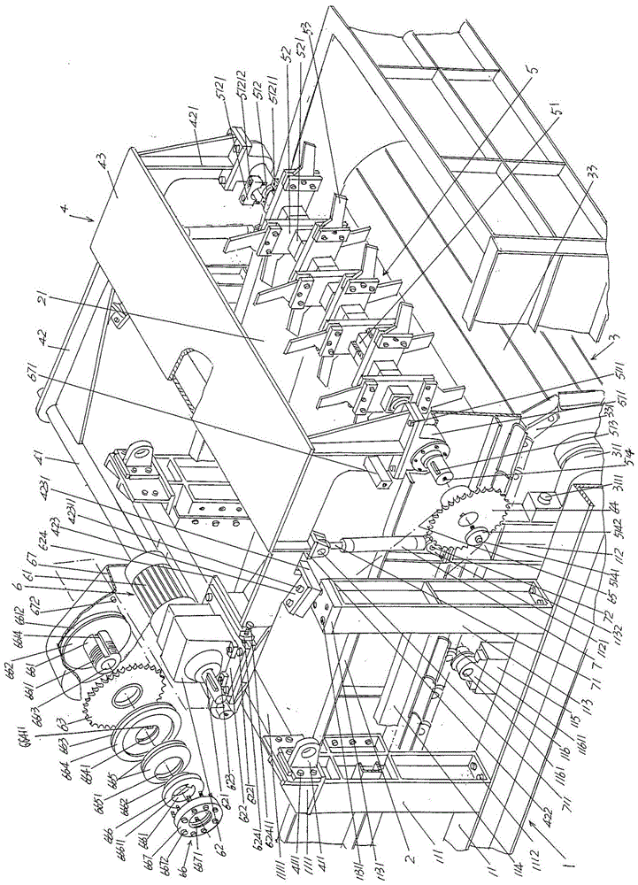
[0027] See figure 1 , provides a frame 1, because the f...


PUM


Abstract

The invention discloses a clay cutting machine and belongs to the technical field of special equipment of the construction material production industry. The clay cutting machine comprises a machine frame, a clay cutting box, a clay ball conveying mechanism, a cantilever support, a clay ball cutting mechanism and a power transmission mechanism, wherein the machine frame is provided with a pair of machine frame beams; the clay cutting box is fixed to the pair of machine frame beams; the clay ball conveying mechanism is located in the cavity of the clay cutting box; the left end of the cantilever support is connected to the position between the pair of machine frame beams, and the right end of the cantilever support is a free end capable of swinging up and down; the clay ball cutting mechanism comprises a cutter rotating shaft, a cutter holder and a cutter, the cutter rotating shaft is supported at the right end of the cantilever support, the middle of the cutter rotating shaft is above the clay ball conveying mechanism correspondingly, the cutter holder is fixed to the middle of the cutter rotating shaft, and the cutter is fixed to the cutter holder; the power transmission mechanism is arranged at the left end of the cantilever support. The clay cutting machine has the advantages that two acting cylinders are arranged at the positions, corresponding to the right end of the cantilever support, of the pair of machine frame beams respectively, and an acting cylinder column of each acting cylinder is upward and is hinged to the right end of the cantilever support. Thus, the cutter is kept away from hard articles and is prevented from being damaged; the cutter rotating shaft is effectively protected and moves stably and enduringly.

Description

technical field [0001] The invention belongs to the technical field of special equipment in the building material production industry, and in particular relates to a clay shredder. Background technique [0002] As known in the industry, the raw materials for producing cement are mainly limestone and clay, and the weight ratio of the two is about four to one. The typical example of the clay referred to here is chalk (the English name is chalk), and chalk is also called white clay powder, white soil, white clay, white good, white sand or chalk, because chalk is a deposit of fine calcium carbonate. and its main component is calcium carbonate (CaCO 3 ), which are widely used as raw materials for the production of cement. [0003] Introducing viscous raw materials such as the aforementioned chalk and limestone into a dual-rotor hammer crusher for crushing in a predetermined volume ratio or weight ratio can achieve the desired mixing and crushing effect, but when encountering a ...

Claims


Application Information

Patent Timeline
Patent Type & Authority Patents(China)
IPC IPC(8): B02C18/14B02C18/16B02C18/18B02C18/22B02C18/24
Inventor 张浩顾鸥明廖正光徐垌伟金鸣
Owner SINOMA CHANGSHU HEAVY MACHINERY
Why Eureka
Try Eureka