Direct-current motor drive circuit and electronic equipment having the circuit

A DC motor and drive circuit technology, applied in the direction of converting DC power input to DC power output, electrical components, and adjusting electrical variables, can solve the problems of high design cost, complex speed control circuit, and PWM square wave signal generation circuit that cannot be adjusted. Air ratio and other issues to achieve the effect of simplifying design difficulty and reducing production cost

Active Publication Date: 2015-11-04
QINGDAO GOERTEK
View PDF7 Cites 2 Cited by
  • Summary
  • Abstract
  • Description
  • Claims
  • Application Information

AI Technical Summary

Problems solved by technology

[0006] The speed control circuit of the existing DC motor is complex, the design cost is high, and the existing PWM square wave signal generating circuit cannot adjust the duty cycle

Method used


Image

  • Direct-current motor drive circuit and electronic equipment having the circuit
  • Direct-current motor drive circuit and electronic equipment having the circuit
  • Direct-current motor drive circuit and electronic equipment having the circuit

Examples


Embodiment Construction

[0045] In order to make the object, technical solution and advantages of the present invention clearer, the implementation manner of the present invention will be further described in detail below in conjunction with the accompanying drawings.

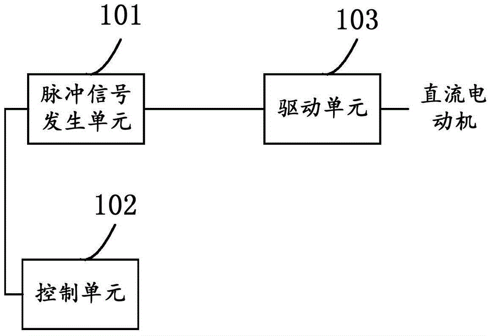
[0046] Such as figure 2 Shown is a schematic structural diagram of a DC motor driving circuit provided by an embodiment of the present invention; the DC motor driving circuit includes: a pulse signal generating unit 101, a control unit 102 and a driving unit 103;

[0047] The pulse signal generating unit 101 is used to generate a DC motor drive pulse signal;

[0048] The control unit 102 is configured to adjust the duty ratio of the driving pulse signal;

[0049] The driving unit 103 is configured to send the adjusted driving pulse signal to the DC motor to drive the DC motor to rotate.

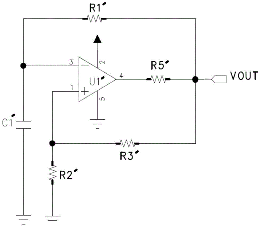
[0050] It should be noted that the pulse signal generating unit includes: a first resistor, a second resistor, a third resistor, a fifth resistor,...


PUM


Abstract

The invention discloses a direct-current motor drive circuit and electronic equipment having the circuit. The direct-current motor drive circuit includes: a pulse signal generation unit, a control unit and a drive unit. The pulse signal generation unit is used for generating a direct-current motor drive pulse signal; the control unit is used for regulating the duty ratio of the drive pulse signal; and the drive unit is used for sending the regulated drive pulse signal to the direct-current motor and driving the direct-current motor to rotate. By adoption of discrete electronic components to constitute the pulse signal generation unit, the control unit and the drive unit, speed control of the direct-current motor is realized, thereby simplifying design difficulty, and reducing production cost.

Description

technical field [0001] The invention relates to the technical field of power electronics, in particular to a DC motor drive circuit and electronic equipment with the circuit. Background technique [0002] At present, DC motors are used in various fields of industry due to their superior speed regulation performance. DC motors can be divided into shunt-excited DC motors, series-excited DC motors and compound-excited DC motors according to their different excitation methods. However, in industry, the speed of a DC motor depends on the voltage applied across it. Usually, the DC motor speed uses a voltage regulating coil to change the voltage at both ends of the DC motor coil to adjust the speed, or a single-chip microcomputer is used to automatically control the speed of the DC motor. [0003] Such as figure 1 As shown, it is a traditional square wave generation circuit diagram, and the working principle of the existing DC motor drive circuit is as follows: [0004] Such as...

Claims


Application Information

Patent Timeline
Patent Type & Authority Applications(China)
IPC IPC(8): H02P7/28H02M3/155
Inventor 刘东宝
Owner QINGDAO GOERTEK
Why Eureka
Try Eureka