Ground terminal of ground wire

A grounding terminal and grounding wire technology, applied in the direction of electrical connection seat, clamping/spring connection, etc., can solve the problems of easy falling, safety accident, plane tilt, etc., and achieve the effect of increasing reliability and preventing safety accidents.

Active Publication Date: 2015-11-04
ELECTRIC POWER RES INST STATE GRID SHANXI ELECTRIC POWER
View PDF5 Cites 10 Cited by
  • Summary
  • Abstract
  • Description
  • Claims
  • Application Information

AI Technical Summary

Problems solved by technology

The grounding point corresponding to the grounding end of the current grounding wire is different in each site, and the current use is clamped on a plane, and there are deficiencies in such a grounding end: First, part of the plane is inclined, and the grounding end is connected to the inclined plane. When the grounding terminal is connected to the angle iron of the tower, it is easy to accidentally bump it and cause it to fall, which will lead to safety accidents.

Method used


Image

  • Ground terminal of ground wire
  • Ground terminal of ground wire
  • Ground terminal of ground wire

Examples


Embodiment 1

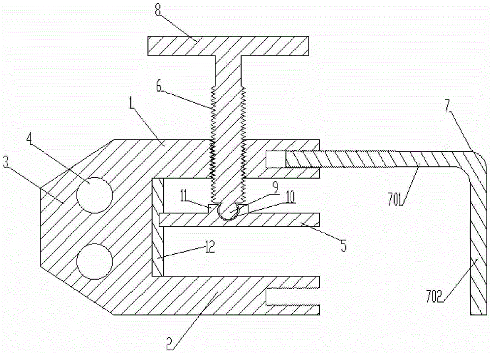
[0031] figure 1 It is a schematic structural diagram of the ground terminal of the ground wire provided in Embodiment 1 of the present invention, Figure 4 It is a schematic diagram of the structure between the intermediate pressure plate and the sliding rod, refer to figure 1 with Figure 4 , The grounding terminal includes a wire clamp body, the wire clamp body includes an upper pressing plate 1, a lower pressing plate 2, and a connecting plate 3 between the upper pressing plate 1 and the lower pressing plate 2. The upper pressing plate 1 and the lower pressing plate 2 are arranged in parallel, so The upper pressing plate 1, the lower pressing plate 2 and the connecting plate 3 are formed as an integral structure, so that the integrity of the grounding terminal is good, and loosening is avoided. The cross-section of the wire clip body is U-shaped, the connecting plate 3 is provided with two wire holes 4, the inside of the wire clip body is provided with a movable middle press...

Embodiment 2

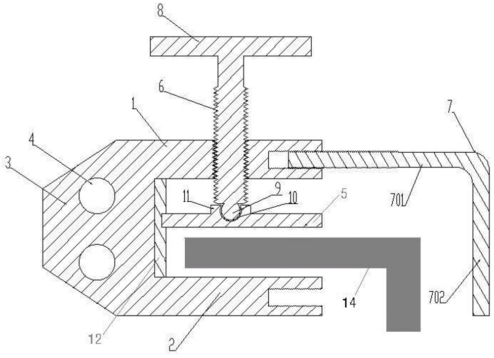
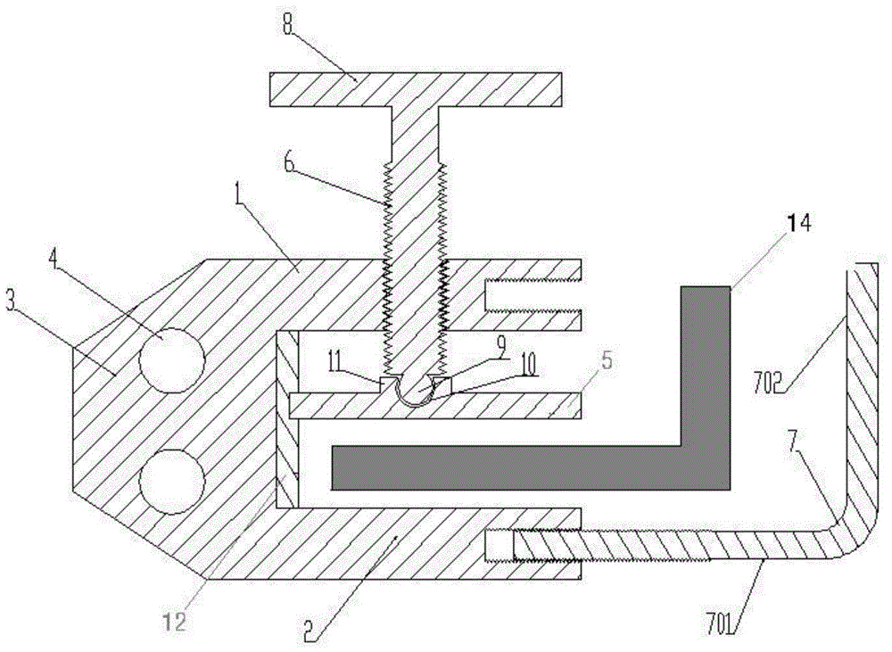
[0036] image 3 It is a schematic diagram of the structure of the ground terminal of the ground wire provided in Embodiment 2 of the present invention, Figure 4 It is a schematic diagram of the structure between the intermediate pressure plate and the sliding rod, refer to image 3 with Figure 4 The grounding terminal includes a wire clamp body, which includes an upper pressure plate 1, a lower pressure plate 2, and a connecting plate 3 between the upper pressure plate 1 and the lower pressure plate 2. The upper pressure plate 1 and the lower pressure plate 2 are arranged in parallel, so The upper pressing plate 1, the lower pressing plate 2 and the connecting plate 3 are an integrated structure, the cross section of the wire clip body is U-shaped, the connecting plate 3 is provided with more than one wire hole 4, the wire clip body There is a movable middle pressing plate 5 inside the middle pressing plate 5, the upper pressing plate 1 and the lower pressing plate 2 are para...


PUM


Abstract

The invention provides a ground terminal of a ground wire. The ground terminal of the ground wire comprises a wire clamp body and is characterized in that the wire clamp body comprises an upper pressing plate, a lower pressing plate and a connecting plate between the upper pressing plate, the upper pressing plate and the lower pressing plate are parallelly arranged, the upper pressing plate, the lower pressing plate and the connecting plate are of an integrally-molded integral structure, the cross section of the wire clamp body is U-shaped, the connecting plate is provided with more than one wire hole, the internal part of the wire clamp body is provided with a movable intermediate pressing plate, the intermediate pressing plate is mutually parallel to the upper pressing plate and the lower pressing plate, the upper pressing plate is provided with a first screw hole, a screw penetrates through the first screw hole with the tail end being fixed on the intermediate pressing plate, the intermediate pressing plate is supported and fixed inside the wire clamp body through the screw, a free end of the upper pressing plate or/and a free end of the lower pressing plate is/are provided with a second screw hole, and an L-shaped screw is screwed in the second screw hole of the upper pressing plate or the lower pressing plate. The ground terminal provided by the invention can enhance the reliability in grounding, and prevents occurrence of safety accidents.

Description

Technical field [0001] The present invention relates to the electrical field, and in particular to a ground terminal of a ground wire. Background technique [0002] The grounding wire is an important safety tool for the daily operation of substations. It is mainly used in safety measures after the equipment is powered off. It grounds all parts of the power that may come in, so as to introduce the current into the earth in the case of sudden power, so as to protect personal safety Purpose, but also effectively protect the safety performance of the equipment. The grounding point corresponding to the grounding terminal of the current grounding wire is different in each site, and the current ones are clamped on a plane, but such grounding terminals have shortcomings: one is that part of the plane is inclined, and the grounding terminal is connected at an inclined plane. When the grounding terminal is connected to the angle iron of the tower, it is easy to accidentally cause the grou...

Claims


Application Information

Patent Timeline
Patent Type & Authority Applications(China)
IPC IPC(8): H01R11/26H01R4/40
Inventor 马啸飞郭锦龙张文波张岩波冀国龙
Owner ELECTRIC POWER RES INST STATE GRID SHANXI ELECTRIC POWER
Why Eureka
Try Eureka