
Fast connecting and positioning device for L-shaped rotary tire and follow fixture of robot and working method of fast connecting and positioning device

A technology of accompanying fixtures and positioning devices, applied in auxiliary devices, manufacturing tools, welding equipment, etc., to achieve the effects of achieving diversity, reducing the number of tooling manufacturing, reducing deformation and robot positioning errors

Active Publication Date: 2015-11-04
CRRC QINGDAO SIFANG CO LTD
View PDF8 Cites 8 Cited by
  • Summary
  • Abstract
  • Description
  • Claims
  • Application Information

AI Technical Summary

Problems solved by technology

[0003] In view of one or more of the above problems, a robot L-shaped rotating tire and accompanying fixture quick connection positioning device and its working method are provided, which can realize automatic grinding, automatic welding, rigid fixture accompanying, and can be used through wedge-shaped surfaces, partial spherical or Hemispherical positioning, fast and accurate compression positioning with longitudinal positioning added to the accompanying fixture, realizes automatic welding, automatic grinding, and tooling fixture accompanying of the side beam manipulator, effectively reducing the number of workpiece disassembly and assembly and beam body welding after disassembly and assembly deformation problem

Method used


Image

  • Fast connecting and positioning device for L-shaped rotary tire and follow fixture of robot and working method of fast connecting and positioning device
  • Fast connecting and positioning device for L-shaped rotary tire and follow fixture of robot and working method of fast connecting and positioning device
  • Fast connecting and positioning device for L-shaped rotary tire and follow fixture of robot and working method of fast connecting and positioning device

Examples


Embodiment Construction

[0043] The present invention will be further described in conjunction with specific embodiments now.

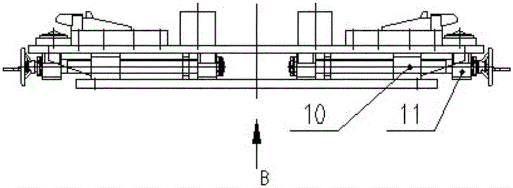
[0044] As shown in the figure, 1 base; 2 positioning block; 3 countersunk screw; 4 bayonet; 6 bayonet seat; 7 slide rail; 9 stopper; 10 movable block; 11 self-locking screw mechanism; 100 accompanying fixture; 101 workpiece; 102 wedge-shaped pressing seat of accompanying fixture.

[0045] The object of the present invention is realized by following preferred embodiments, and structure and composition are as follows:

[0046] (1) The base 1 is connected with the transition plate of the robot L rotating tire positioner, and the self-locking screw mechanism is used to build and connect the front wedge block to move with the screw and position and tighten along the slide rail.

[0047] (2) The main structure includes piece 1 base, piece 2 positioning block, piece 4 bayonet, piece 6 bayonet seat, piece 7 slide rail, piece 9 stopper, piece 10 movable block, piece 11 self-locking s...


PUM


Abstract

The invention provides a fast connecting and positioning device for an L-shaped rotary tire and a follow fixture of a robot and a working method of the fast connecting and positioning device. A base is provided with symmetric follow fixture fast connector devices. The follow fixture fast connector devices comprise bayonet pins, bayonet pin seats and sliding rails. The sliding rails are arranged on the base. The bayonet pin seats freely slide on the sliding rails in the horizontal direction. The bayonet pin seats are connected with self-locking lead screw mechanisms or hydraulic jacking mechanisms. The bayonet pins are fixed to the bayonet pin seats. The bayonet pins are each of a blocky structure. The bottom faces of the bayonet pins are provided with slopes or wedge-shaped surfaces, and the slopes or the wedge-shaped surfaces and the wedge-shaped surface of the follow fixture are fast positioned. The base is provided with transverse and longitudinal positioning blocks with slopes. Dowel seats are arranged on the outer sides of the bayonet pin seats. The dowel seats are internally provided with part of spherical or semi-spherical dowels, and the part of spherical or semi-spherical dowels and the concave surface of the follow clamp are matched and fast positioned. Stopping blocks can be arranged at the inward ends of the bayonet pin seats in the longitudinal direction. Automatic welding and automatic grinding of a side beam mechanical arm and work fixture following are achieved, and the workpiece dismounting and mounting frequency and the problems of beam body welding deformation caused after dismounting and mounting are finished are effectively reduced.

Description

technical field [0001] The invention belongs to the field of welding and grinding process manufacturing of bogie side beams, in particular to a device for fast connection and positioning of L-shaped tires of robots and accompanying clamps, and is especially suitable for automatic welding and automatic grinding of subway side beams. Background technique [0002] During the welding process of the side beam of the bogie, the side beam needs to be assembled and welded with internal ribs and then hoisted into the rigid accompanying fixture fixed on the manipulator. After the manipulator is welded, it needs to wait for sufficient cooling before reassembling and welding. On the rigid accompanying fixture of the tire, the accompanying fixture is released after the secondary outer body welding of the manipulator is completed, hoisted to the automatic grinding tire position, and the automatic grinding of the manipulator is completed. Due to the deformation of the beam body after repea...

Claims


Application Information

Patent Timeline
IPC IPC(8): B23K37/047B24B41/00B24B41/06B23K101/26
CPCB23K37/047B23K2101/26B24B41/00B24B41/067
Inventor 吴向阳张志毅王心红陶传琦周超王银灵万里陈龙迟建波
Owner CRRC QINGDAO SIFANG CO LTD
Learn More