
Bundling band disk mechanism

A technology of belt reel and deceleration motor, which is applied in the direction of conveying filamentous materials, thin material processing, transportation and packaging, etc. It can solve the problems of high cost, difficult implementation, inconvenient disassembly and maintenance, and achieve increased expansion and contraction Range, the effect of realizing the expansion and contraction function

Inactive Publication Date: 2015-10-28
CHINA NAT HEAVY MACHINERY RES INSTCO
View PDF9 Cites 15 Cited by
  • Summary
  • Abstract
  • Description
  • Claims
  • Application Information

AI Technical Summary

Problems solved by technology

[0002] In all kinds of strapping equipment, strapping reels are required to complete the support, fixation and uncoiling of the strapping straps. The traditional strapping reels have complex structure design, high cost, inconvenient disassembly and maintenance, and are not easy to implement.

Method used


Image

  • Bundling band disk mechanism

Examples


Embodiment Construction

[0011] The present invention will be described in detail below in conjunction with the accompanying drawings.

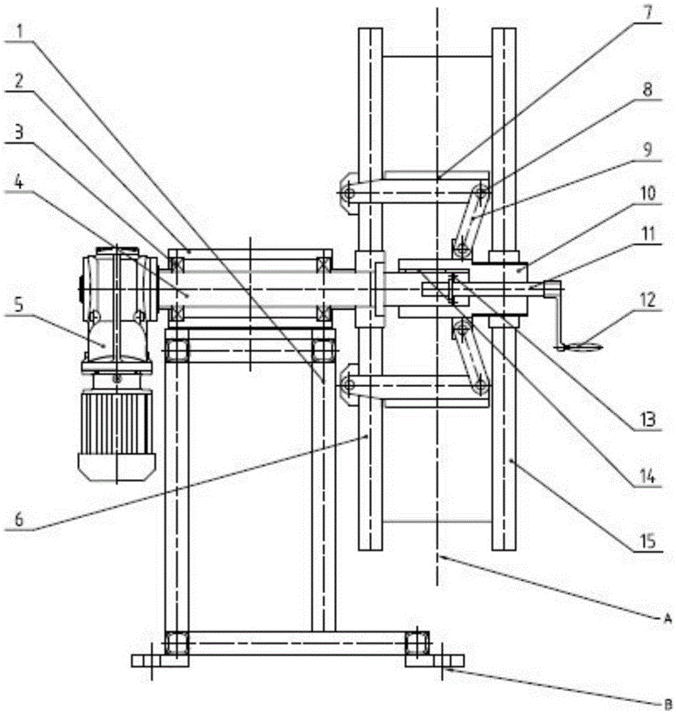
[0012] Referring to the accompanying drawings, a strapping reel mechanism includes a base 1, a bearing seat 2 is fixed on the base 1, a rotating shaft 4 is supported on a bearing 3 in the bearing seat 2, and the left end of the rotating shaft 4 is connected with a decelerating motor 5, and the decelerating motor 5 The rotating shaft 4 is driven to rotate, and the shaft shoulder of the rotating shaft 4 is connected with the inner guard plate 6. There are no less than two hinged joints on the outer side of the inner guard plate 6, and each hinged joint is hinged with one end of the expansion-contraction plate 7 through a pin shaft 8, and the expansion-contraction plate 7 is hinged. 7 The other end is hinged with one end of the chain plate 9 through the pin shaft 8, and the other end of the chain plate 9 is hinged with the hinge joint above the screw sleeve 10 through th...


PUM


Abstract

The invention provides a bundling band disk mechanism. A rotary shaft is supported by a bearing in a bearing block. A speed reduction motor is connected with the end of the rotary shaft and drives the rotary shaft to rotate. An inner guard plate is connected with the shaft shoulder of the rotary shaft. The outer side of the inner guard plate is provided with two or more hinged ports. The hinged ports are hinged to expansion and shrinkage plates, chain plates and a thread sleeve through pin shafts in sequence. The thread sleeve slides on the rotary shaft through a guide key on the rotary shaft but does not rotate. The thread sleeve is connected with an external thread of a threaded rod through an internal thread. The threaded rod is made to rotate but does not move under the restraint of a baffle; a handle connected to the end of the threaded rod is rotated to drive the thread sleeve to move forwards and backwards, so that the chain plates are driven to move, the included angle between the chain plates and the corresponding expansion and shrinkage plates is changed, the expansion and shrinkage functions are achieved, and a bundling band is supported and fixed. An internal thread in the center of the outer guard plate and an external thread of the thread sleeve are connected, so that the two end faces of the bundling band are fixed, and finally the speed reduction motor is used for driving the rotary shaft to drive a whole bundling band disk to rotate and uncoil the bundling band. The bundling band disk mechanism is simple in structure and high in practicality.

Description

technical field [0001] The invention relates to the technical field of metallurgical equipment, in particular to a strapping reel mechanism. Background technique [0002] All kinds of strapping equipment need to be equipped with a strapping reel to complete the support, fixation and unwinding of the strapping. The traditional strapping reel has a complex structure design, high cost, inconvenient disassembly and maintenance, and is not easy to implement. Contents of the invention [0003] In order to overcome the above-mentioned defects in the prior art, the object of the present invention is to provide a strapping reel mechanism, which has a simple structure, strong practicability, and is easy to implement. [0004] In order to achieve the above object, technical scheme of the present invention is: [0005] A strapping reel mechanism, comprising a base 1, a bearing seat 2 is fixed on the base 1, a rotating shaft 4 is supported on a bearing 3 in the bearing seat 2, the lef...

Claims


Application Information

Patent Timeline
IPC IPC(8): B65H75/24B65H75/14B65H54/547
Inventor 张康武郭韡高文辉浦文杰许展望
Owner CHINA NAT HEAVY MACHINERY RES INSTCO
Learn More