A kind of pneumatic current receiver at the lower part of the third rail

A current collector and current collector shoe technology, which is applied in the field of pneumatic current collectors at the lower part of the third rail, to achieve good coupling and current collection effects

Active Publication Date: 2019-02-15
湖南中通电气股份有限公司
View PDF7 Cites 2 Cited by
  • Summary
  • Abstract
  • Description
  • Claims
  • Application Information

AI Technical Summary

Problems solved by technology

[0003] The purpose of the present invention is to solve the technical problem that the existing subway vehicle three-rail current collector needs to use multiple cylinders to realize pneumatic and manual boot removal or reset, so as to provide a pneumatic and manual boot removal with only one cylinder. Or reset function, installation, maintenance, easy to use, less fault points and reliable dynamic follow performance of the third rail lower pneumatic current collector

Method used


Image

  • A kind of pneumatic current receiver at the lower part of the third rail
  • A kind of pneumatic current receiver at the lower part of the third rail
  • A kind of pneumatic current receiver at the lower part of the third rail

Examples


Embodiment 1

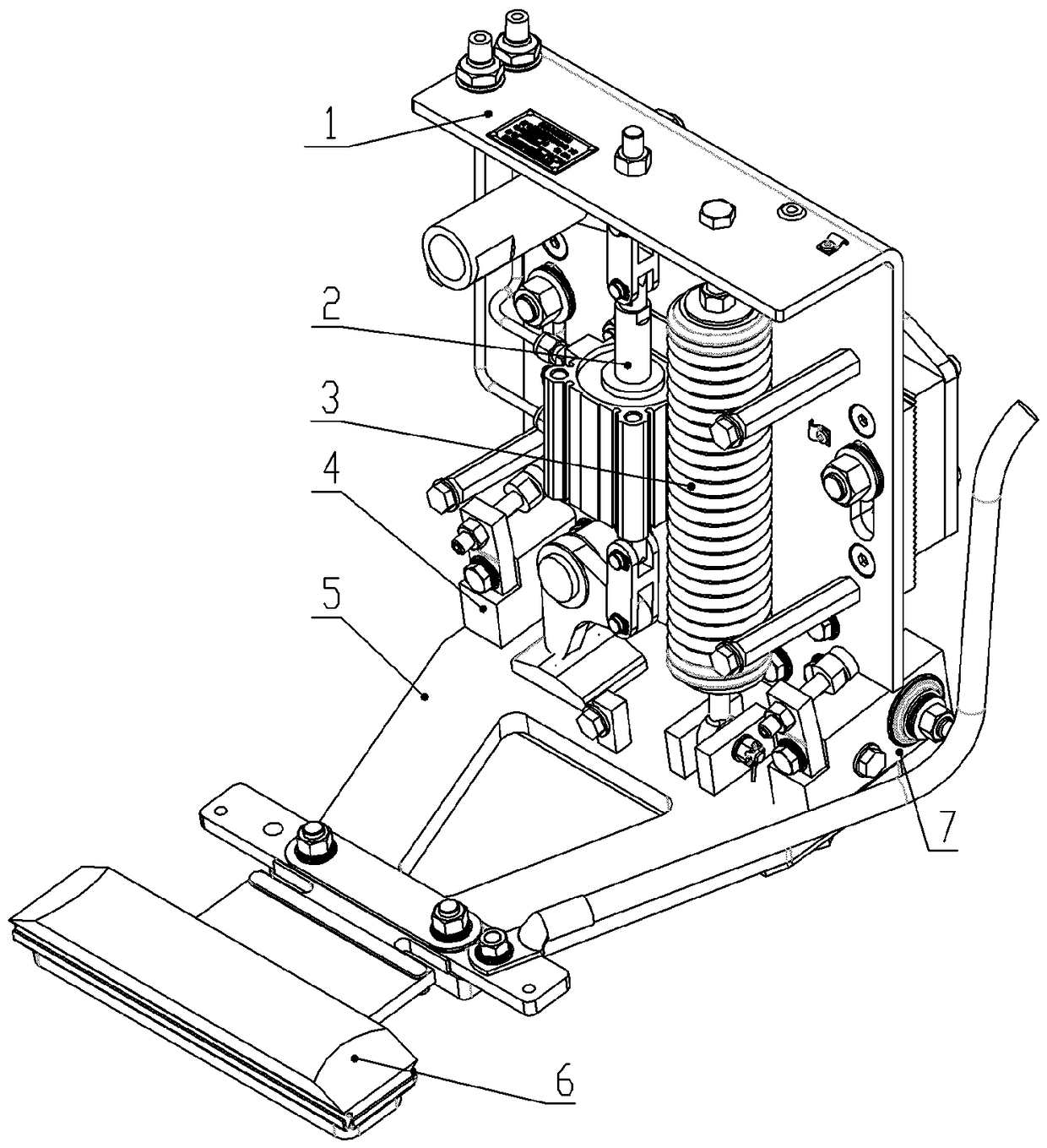
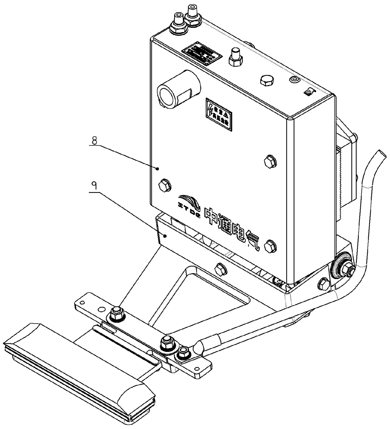
[0019] Embodiment 1, the present invention is installed on the back plate assembly 1, the cylinder and the upper and lower crank connecting rod assembly 2 connected, the tension spring assembly 3, the left and right flexible bearing seats 4 and 7 connected to the swing arm, and the insulating swing arm 5. The flow receiving shoe 6 on the swing arm, the upper insulating shield 8 and the lower insulating shield 9 etc. constitute the lower pneumatic current collector. Cylinder and connected upper and lower crank and connecting rod assembly 2 only need to use a double-acting cylinder, the lower end piston rod of the double-acting cylinder is connected to the shoe-off crank through the connecting rod, and the acting force is on the swing arm to make the swing arm swing downward, so that the flow receiving Pneumatic shoe removal is realized when the sliding shoe is separated from the third rail, or the shoe removal crank does not act on the swing arm and the swing arm swings upward u...

Embodiment 2

[0020] Embodiment 2, the cylinder of the present invention and the connected upper and lower crank and connecting rod assembly 2. The piston rod at the lower end of the cylinder is connected to the boot-off crank and the manual boot-off crank connected to the upper piston rod. When the boot-off crank makes the swing arm reach the boot-off position At or slightly past bottom dead center. A limit adjustment bolt is set on the top of the manual boot-off crank, and the position can be adjusted slightly so that the boot-off crank can be kept at the bottom dead center or slightly past the bottom dead point, and it can be held against the swing arm to maintain the boot-off position. Close the air source without being in a long-term ventilation working state. refer to figure 1 and Figure 4 , and the rest are the same as Example 1.

Embodiment 3

[0021] Embodiment 3, the left and right flexible bearing seats 4 and 7 connecting the swing arm and the back plate of the present invention adopt rubber elastic bearings, which can connect the swing arm and make the swing arm swing at a certain angle, so that when the current receiver operates normally, the current receiver can be guaranteed Adapt to the irregularity changes of the three rails and the wear changes of the current collector shoes, realize the automatic adjustment of the elastic components of the current receiver, balance and maintain the good coupling and current reception between the current collector shoes and the three rails, and play a role in damping vibrations to highlight its Good dynamic following performance of the receiver. refer to figure 1 and Figure 4 , and the rest are the same as Example 1.


PUM


Abstract

The invention provides a third-rail lower pneumatic current collector. Technical problems of the traditional three-rail lower pneumatic current collector for a rail transit vehicle that a plurality of cylinders are used, a plurality of gas circuits are arranged, the operation is complicated, the cost is high and the like are mainly solved. The third-rail lower pneumatic current collector is characterized by comprising a mounting back plate assembly(1), a cylinder crank connecting rod assembly(2), a tension spring assembly (3), a left flexible bearing seat (4), a right flexible bearing seat (7), an insulated swinging arm (5), a current collecting slip shoe (6), an upper insulated protective cover (8), a lower insulated protective cover (9) and the like, wherein the left flexible bearing seat (4) and the right flexible bearing seat (7) are connected with the swinging arm; and the current collecting slip shoe (6) is mounted on the swinging arm (5). As only one cylinder is needed to be connected with a shoe derailing crank assembly, the third-rail lower pneumatic current collector provided by the invention, is simply and reliably structured and convenient to operate and maintain. The third-rail lower pneumatic current collector provided by the invention can be widely applied tovarious three-rail current collectors for the rail transit vehiclesor used for improving the original current collectors.

Description

technical field [0001] The invention relates to a current collector, which is a pneumatic current collector for the lower part of the third rail used in rail transit vehicles. Background technique [0002] At present, two or more cylinders are used to realize the pneumatic and manual shoe-off functions of the existing three-rail lower pneumatic current collector for rail transit vehicles. Many cylinders are used, the cost is high, the maintenance and repair are inconvenient, and the safety and reliability are poor. Contents of the invention [0003] The purpose of the present invention is to solve the technical problem that the existing subway vehicle three-rail current collector needs to use multiple cylinders to realize pneumatic and manual boot removal or reset, so as to provide a pneumatic and manual boot removal with only one cylinder. Or reset function, installation, maintenance, easy to use, fewer failure points and reliable dynamic follow performance of the third ...

Claims


Application Information

Patent Timeline
Patent Type & Authority Patents(China)
IPC IPC(8): B60L5/39
Inventor 谭协民汪永明陈革程卫群肖洪源
Owner 湖南中通电气股份有限公司
Why Eureka
Try Eureka