Winding method of large-diameter hemispherical fiber composite material
A fiber composite material and large-diameter technology, applied in the field of material science, can solve the problems of low molding efficiency, large investment, and high cost, and achieve the effect of reducing the workload and solving the large amount of calculation
- Summary
- Abstract
- Description
- Claims
- Application Information
AI Technical Summary
Problems solved by technology
Method used
Image
Examples
specific Embodiment approach 1
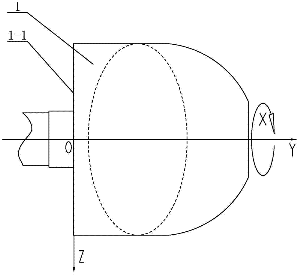
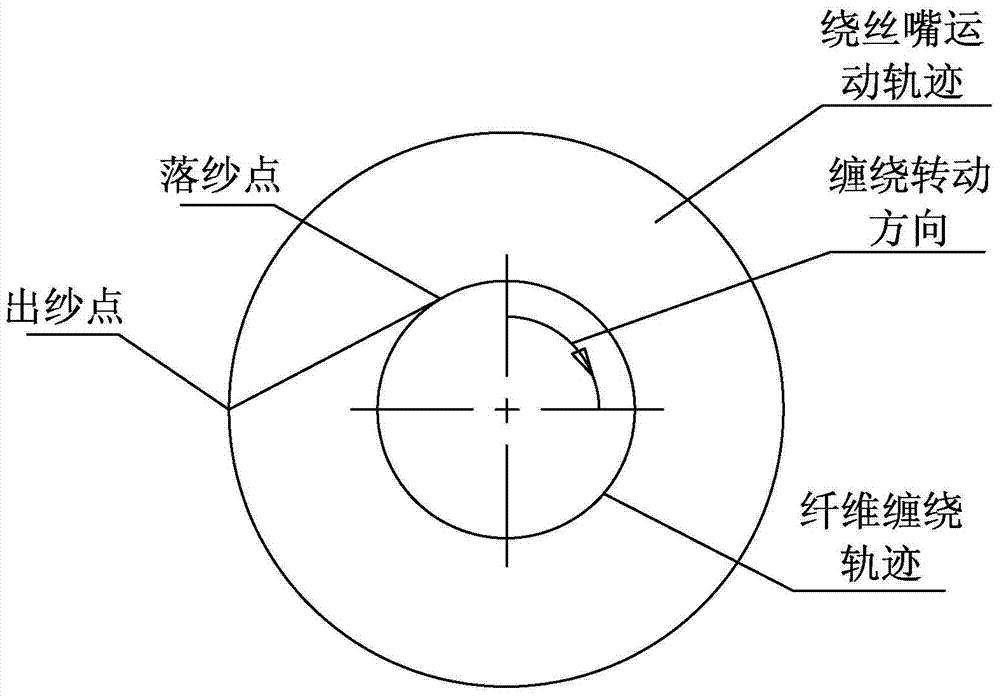
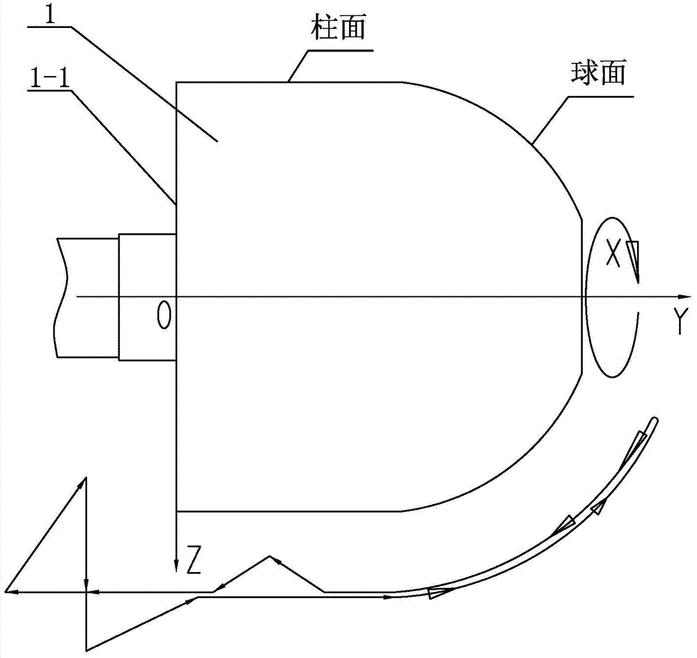
[0015] Specific implementation mode one: combine Figure 1 to Figure 4 To illustrate this embodiment, a large-diameter hemispherical fiber composite material winding method described in this embodiment is realized through the following steps:
[0016] Step 1. Establish winding coordinate system:
[0017] Take the geometric center of the flat head 1-1 of mandrel 1 as the origin, take the axial direction of mandrel 1 as Y axis, take the radial direction of mandrel 1 as Z axis, and take the circumferential direction of mandrel 1 as X axis to establish XOYZ coordinate system;
[0018] Step 2, determine the winding track;
[0019] Step 3. Determine the trajectory of the wire winding nozzle;
[0020] Step 4. Calculating the movement coordinates of the winding nozzle, setting a number of control points on the hemispherical fiber winding trajectory, and calculating the movement coordinates of the winding nozzle in the hemispherical part respectively;
[0021] Step five, suturing t...
specific Embodiment approach 2
[0023] Specific implementation mode two: combination Figure 1 to Figure 4 Describe this embodiment, a large-diameter hemispherical fiber composite material winding method described in this embodiment, characterized in that: the specific steps for calculating the movement coordinates of the wire winding nozzle in step 4 are as follows:
[0024] Step 4 (1), input the original data, the original data includes the radius R of the hemisphere, the length L of the simple tube, and the distance S between the winding nozzle and the spherical surface t , barrel section winding angle α, advance amount B in sand width direction;
[0025] Step 4 (2), calculate the distance between the doffing point and the winding nozzle:
[0026]
[0027] Step four (three), calculate the spherical X coordinate:
[0028] The spherical part has n control points i=0·····n, M i =arctg{(sinα)·tg[β i +arctg(F / R)]}
[0029] If M i >X i-1 Then X i = M i , if M i ≤X i-1 Then X i =180+M i , where M...
specific Embodiment approach 3
[0044] Specific implementation mode three: combination Figure 1 to Figure 4 Describe this embodiment, a large-diameter hemispherical fiber composite material winding method described in this embodiment, is characterized in that: in step 6, the specific steps for processing the core-to-mold winding ratio of the winding track are as follows:
[0045] Step six (1), calculate the winding speed ratio:
[0046]
[0047] i in formula (4) 0 Indicates the winding speed ratio, X i Indicates the rotation angle of the principal axis at the spherical surface, X′ i Indicates the spindle rotation angle at the cylindrical surface, X″ i Indicates the spindle angle at the plane;
[0048] Step 6 (2), rounded to:
[0049] i in formula (5) 0 Represents the winding speed ratio, M represents a positive integer, k / n represents the simplest true fraction, n represents the number of tangent points, B represents the design width of the yarn piece, D represents the diameter of the cylinder;
...
PUM
 Abstract
Description
Claims
Application Information
 - R&D Engineer
- R&D Manager
- IP Professional
- Industry Leading Data Capabilities
- Powerful AI technology
- Patent DNA Extraction
Browse by: Latest US Patents, China's latest patents, Technical Efficacy Thesaurus, Application Domain, Technology Topic, Popular Technical Reports.
© 2024 PatSnap. All rights reserved.Legal|Privacy policy|Modern Slavery Act Transparency Statement|Sitemap|About US| Contact US: help@patsnap.com


