
Large-diameter hemispherical fibrous composite winding method

A fiber composite material and large-diameter technology, which is applied in the field of material science, can solve the problems of large investment, low molding efficiency, and high cost, and achieve the effect of solving a large amount of calculation and reducing the workload

Active Publication Date: 2015-10-28
HARBIN FRP INST +1
View PDF4 Cites 0 Cited by
  • Summary
  • Abstract
  • Description
  • Claims
  • Application Information

AI Technical Summary

Problems solved by technology

[0004] In order to solve the problems of large investment, high cost and low molding efficiency in the existing molding tec

Method used


Image

  • Large-diameter hemispherical fibrous composite winding method
  • Large-diameter hemispherical fibrous composite winding method
  • Large-diameter hemispherical fibrous composite winding method

Examples


specific Embodiment approach 1

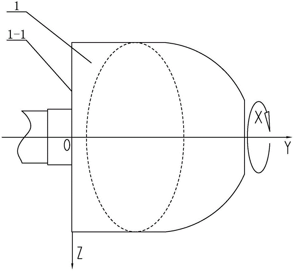
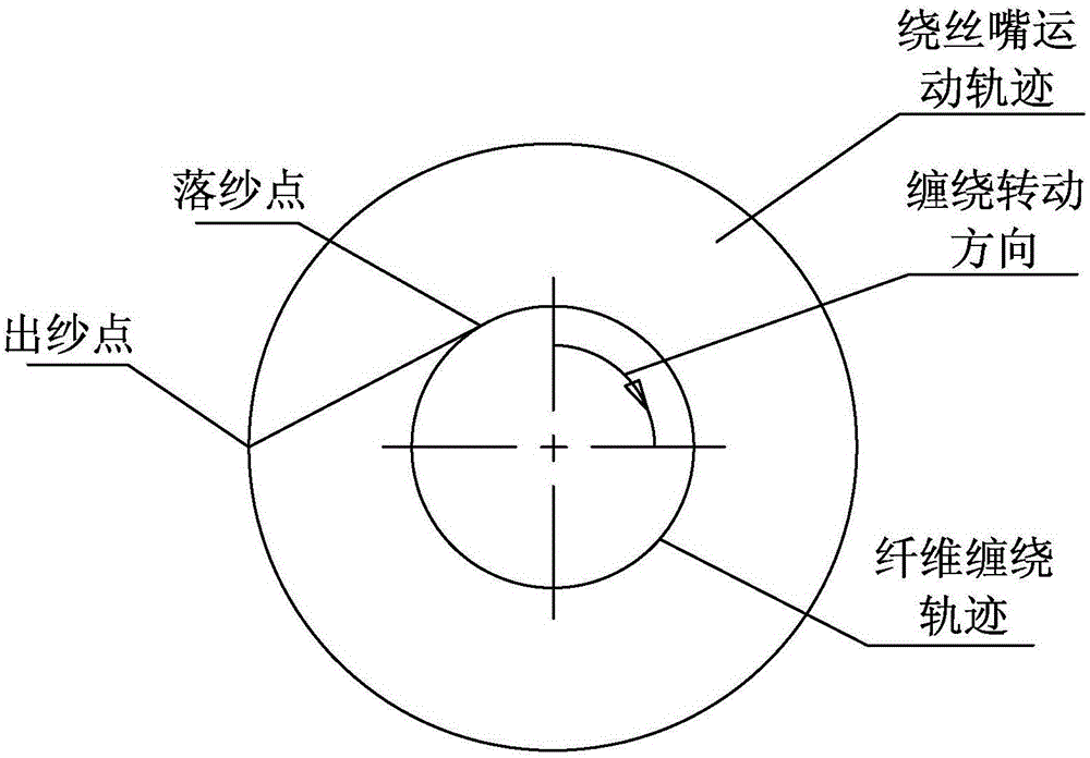
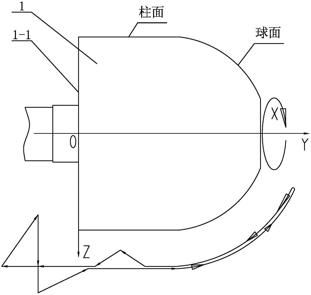
[0015] Specific implementation mode one: combine Figure 1 to Figure 4 To illustrate this embodiment, a large-diameter hemispherical fiber composite material winding method described in this embodiment is realized through the following steps:

[0016] Step 1. Establish winding coordinate system:

[0017] Take the geometric center of the flat head 1-1 of mandrel 1 as the origin, take the axial direction of mandrel 1 as Y axis, take the radial direction of mandrel 1 as Z axis, and take the circumferential direction of mandrel 1 as X axis to establish XOYZ coordinate system;

[0018] Step 2, determine the winding track;

[0019] Step 3. Determine the trajectory of the wire winding nozzle;

[0020] Step 4. Calculating the movement coordinates of the winding nozzle, setting a number of control points on the hemispherical fiber winding trajectory, and calculating the movement coordinates of the winding nozzle in the hemispherical part respectively;

[0021] Step five, suturing t...

specific Embodiment approach 2

[0023] Specific implementation mode two: combination Figure 1 to Figure 4 Describe this embodiment, a large-diameter hemispherical fiber composite material winding method described in this embodiment, characterized in that: the specific steps for calculating the movement coordinates of the wire winding nozzle in step 4 are as follows:

[0024] Step 4 (1), input the original data, the original data includes the radius R of the hemisphere, the length L of the simple tube, and the distance S between the winding nozzle and the spherical surface t , barrel section winding angle α, advance amount B in sand width direction;

[0025] Step 4 (2), calculate the distance between the doffing point and the winding nozzle:

[0026] F = ( R + S t ) 2 ...

specific Embodiment approach 3

[0044] Specific implementation mode three: combination Figure 1 to Figure 4 Describe this embodiment, a large-diameter hemispherical fiber composite material winding method described in this embodiment, is characterized in that: in step 6, the specific steps for processing the core-to-mold winding ratio of the winding track are as follows:

[0045] Step six (1), calculate the winding speed ratio:

[0046] i 0 = Σ i = 0 i = n ( X i ) + Σ i = 0 i = ...


PUM


Abstract

The invention relates to a winding method, in particular to a large-diameter hemispherical fibrous composite winding method, and belongs to the field of material science. The method aims to solve the problems that an existing molding technology is high in investment and cost and low in molding efficiency. The method comprises the steps that firstly, a winding coordinate system is established, wherein the geometric center of a plane head of a core model is used as an original point, the axial direction of the core model is used as a Y-axis, the radial direction of the core model is used as a Z-axis, and the peripheral direction of the core model is used as an X-axis to establish an XOYZ coordinate system; secondly, a winding path is determined; thirdly, the motion path of a wire winding nozzle is determined; fourthly, the motion coordinates of the wire winding nozzle are calculated, and multiple control points are set on a hemispherical filament winding path to calculate the motion coordinates of the wire winding nozzle respectively; fifthly, the stitching points of the motion path of the wire winding nozzle are stitched; sixthly, the core model winding ratio of the winding path is treated.

Description

technical field [0001] The invention relates to a winding method, in particular to a winding method of a large-diameter hemispherical fiber composite material, and belongs to the field of material science. Background technique [0002] The winding molding process is a process technology in which the continuous fiber soaked in the resin glue is wound on the mandrel according to certain rules, and then solidified and demoulded to obtain the product. The filament winding molding process is divided into three types: dry winding, wet winding and semi-dry winding. Dry winding is to use prepreg treated prepreg yarn or tape, which is heated and softened to a viscous state on the winding machine and then wound onto the mandrel. Since the prepreg yarn (or belt) is professionally produced, the resin content (accurate to within 2%) and the quality of the prepreg yarn can be strictly controlled. Therefore, dry winding can accurately control product quality. The biggest feature of the ...

Claims


Application Information

Patent Timeline
IPC IPC(8): B29C70/38
CPCB29C70/382
Inventor 赵洪斌娄小杰侯传礼
Owner HARBIN FRP INST
Learn More