a jig head

A fixture head and integrated technology, applied in the direction of manufacturing tools, workpiece clamping devices, electrolysis process, etc., can solve the problems of affecting the service life of the fixture head, increasing the operating cost of the enterprise, and corrosion of the fixture head, so as to achieve a simplified structure and high production efficiency , reduce the effect of corrosion

Active Publication Date: 2017-09-29
高志成
View PDF6 Cites 0 Cited by
  • Summary
  • Abstract
  • Description
  • Claims
  • Application Information

AI Technical Summary

Problems solved by technology

The gripper products used in this process, such gripper heads as Figure 9 As shown, it is generally composed of a left clip assembly 1', a right clip assembly 2', a spring 6', and a pin 7'. The left clip assembly 1' and the right clip assembly 2' cooperate with each other through the spring 6' and the pin 7' And hinged together, this type of fixture head has the following disadvantages: First, it needs to pre-produce each part before assembly during production, which takes a long time for assembly and low efficiency, which increases the operating cost of the enterprise; second, On the sides of the left clip assembly and the right clip assembly of the clamp head, grooves 8' for embedding springs are respectively provided. In addition, there are many gaps 9' at the hinge (such as the gap between the spring pin and the spring) , the gap between the pin and the left clip assembly, the right clip assembly, etc.), so that the product is easy to store the electroplating solution or electrophoretic fluid during use, which not only consumes a part of the electroplating solution or electrophoretic fluid in vain, but also electroplating solution or electrophoretic fluid The electrophoretic liquid is stored and dried in the slot, and it will also cause great corrosion to the fixture head, which greatly affects the service life of the fixture head

Method used


Image

  • a jig head
  • a jig head
  • a jig head

Examples


Embodiment approach

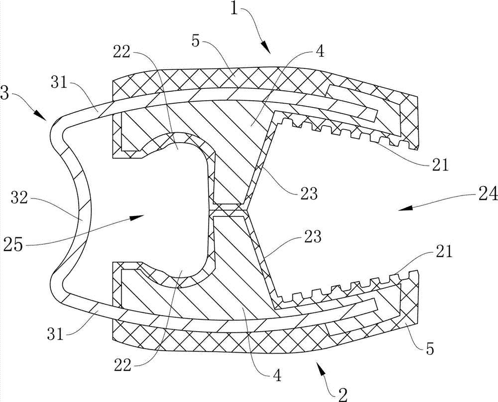
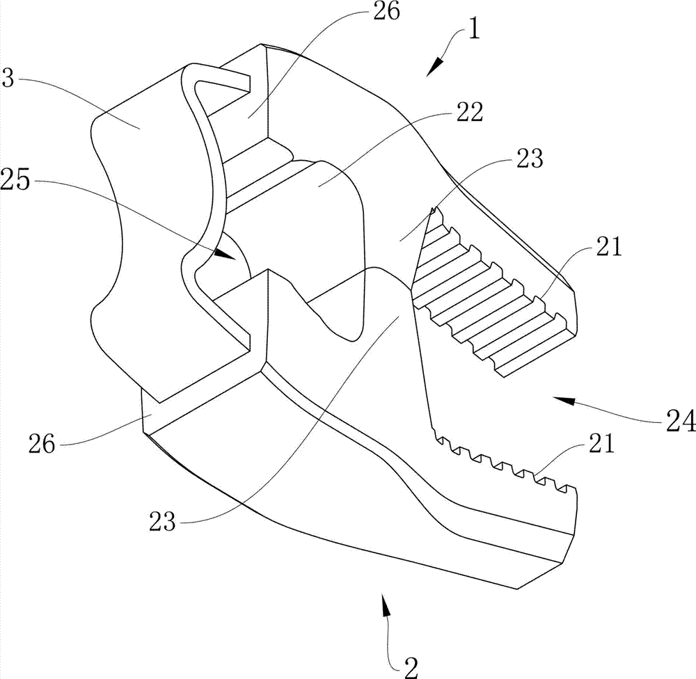
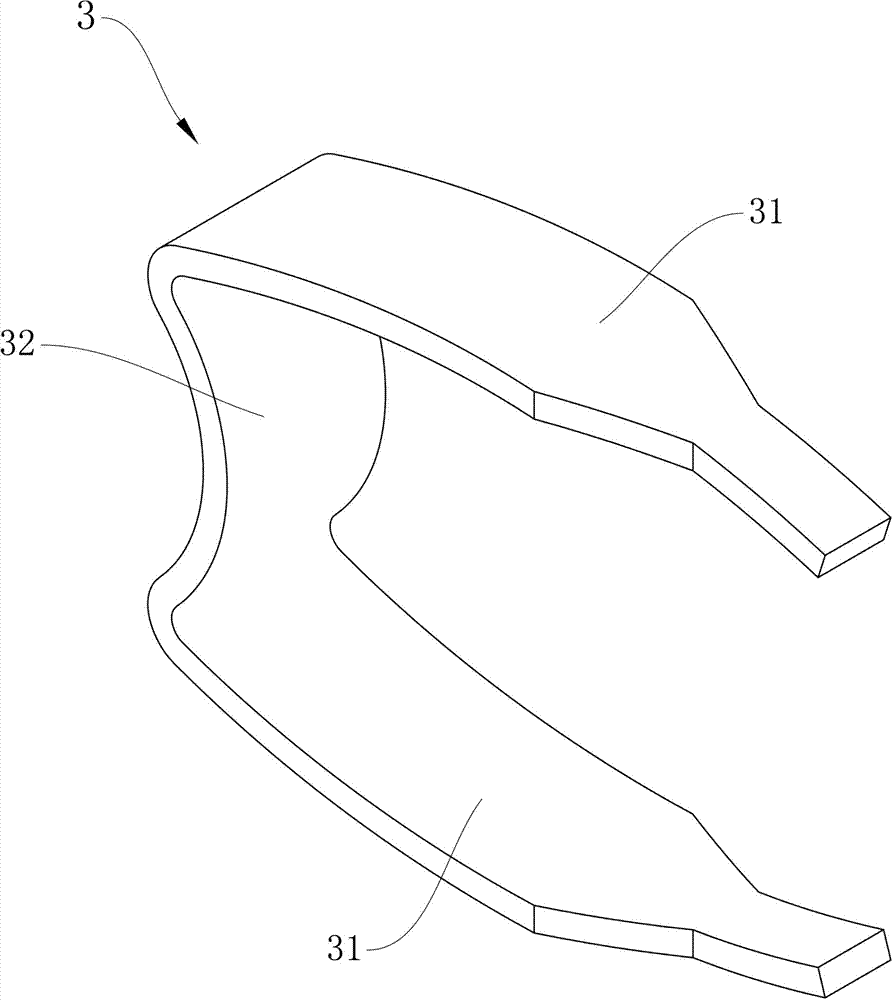
[0019] A class is, for example Figure 1 to Figure 6 As shown, the elastic tension connector 3 is composed of two connection parts 31 and an elastic tension part 32 disposed between the two connection parts 31 . Among them such as Figure 4 As shown, the elastic tensioning portion 32 is formed with an inwardly concave arc concave surface 30, and an outwardly arched arc transition portion is also formed at the connection between the elastic tensioning portion 32 and the two connecting portions 31 40, the two connecting parts 31 are respectively bent into an arc-shaped shape 50 that is relatively outwardly arched. Through such a structural design, the left clamping assembly 1 and the right clamping assembly 2 can obtain better tension elasticity, and are more reliable and firm when clamping objects. On the basis of this scheme, according to the different cross-sectional shapes of the connecting part 31 and the elastic tension part 32, two schemes can be extended: one is imag...


PUM


Abstract

The invention relates to a non-dirt-hidden fixture head in an extremely simplified structure. The fixture head is characterized in that the fixture head comprises a left clamp assembly, a right clamp assembly, and an elastic tensioning connecting piece; the elastic tensioning connecting piece is connected with the rear ends of left clamp assembly and the right clamp assembly into a whole; the left clamp assembly, the right clamp assembly and the elastic tensioning connecting piece are made of mutually different materials and are subjected to once connection forming; a clamp mouth in a normally open state is formed between the front ends of the left clamp assembly and the right clamp assembly; an operation chamber slotted hole is formed between the rear ends of the left clamp assembly and the right clamp assembly in a defined manner; and an operation tool can penetrate through and be nested into the operation chamber slotted hole. The structure of the fixture head is extremely simplified, no assembly is required, and the fixture head is formed by once processing, so that the labor cost is saved; the production efficiency is high; the production cost can be reduced greatly; the fixture head has no gap, groove or recess, so that the fixture head can not hide a treating fluid or dirt; the wastage of the treating fluid can be reduced greatly; the corrosion to a fixture from the treating fluid can be reduced greatly; the service life of the fixture is prolonged; resource saving is facilitated greatly; the pollution discharge is reduced; and the preservation of the natural environment is facilitated.

Description

technical field [0001] The invention relates to a fixture product used in electroplating, electrophoresis, oxidation spraying, planing and other processes in the metal surface treatment industry. Background technique [0002] In the process of electroplating and electrophoresis treatment of aluminum profiles, in order to quickly fix the aluminum profiles, put them into the electroplating or electrophoresis tank for electroplating or electrophoresis, oxidation treatment, etc., the clamp head is generally used to clamp and fix the aluminum profiles in the electroplating or electrophoresis tank. Electrophoresis rack, and then put them together into the electroplating or electrophoresis tank for processing. The gripper products used in this process, such gripper heads as Figure 9 As shown, it is generally composed of a left clip assembly 1', a right clip assembly 2', a spring 6', and a pin 7'. The left clip assembly 1' and the right clip assembly 2' cooperate with each other th...

Claims


Application Information

Patent Timeline
Patent Type & Authority Patents(China)
IPC IPC(8): C25D17/08B25B11/00
CPCB25B11/00
Inventor 高志成
Owner 高志成
Why Eureka
Try Eureka