Method for calibrating focal plane of invisible light transmission optical system through supplementary lens

A technology for attaching lenses and optical systems, applied in the field of optical detection, can solve the problems of difficult operation, difficult to meet, low efficiency, etc., and achieve the effect of strong operability, strong adaptability and low cost

Active Publication Date: 2015-10-21
NANJING ZHONGKE ASTROMOMICAL INSTR
View PDF10 Cites 2 Cited by
  • Summary
  • Abstract
  • Description
  • Claims
  • Application Information

AI Technical Summary

Problems solved by technology

[0002] Generally, simple invisible light transmission optical systems (such as near-ultraviolet and near-infrared bands) are not achromatized with visible light, such as aplanatic single lenses. When calibrating the focal plane position of the system, the invisible light band used is usually calculated based on the focus of visible light. For the lower focal plane position, the error of calibrated focal plane position is relatively large. For optical systems with smaller focal depth and higher image quality requirements, it is even more difficult to meet the requirements of focal plane calibration.
In the process of specific implementation, it is also necessary to ensure the concentricity and axial position of the focal plane assembly and the optical axis, which is difficult to operate and low in efficiency.

Method used


Image

  • Method for calibrating focal plane of invisible light transmission optical system through supplementary lens
  • Method for calibrating focal plane of invisible light transmission optical system through supplementary lens
  • Method for calibrating focal plane of invisible light transmission optical system through supplementary lens

Examples


Embodiment Construction

[0022] The present invention will be described in further detail below in conjunction with the accompanying drawings.

[0023] The present invention provides a method for calibrating the focal plane of an invisible light transmission optical system with an additional lens, specifically comprising the following steps:

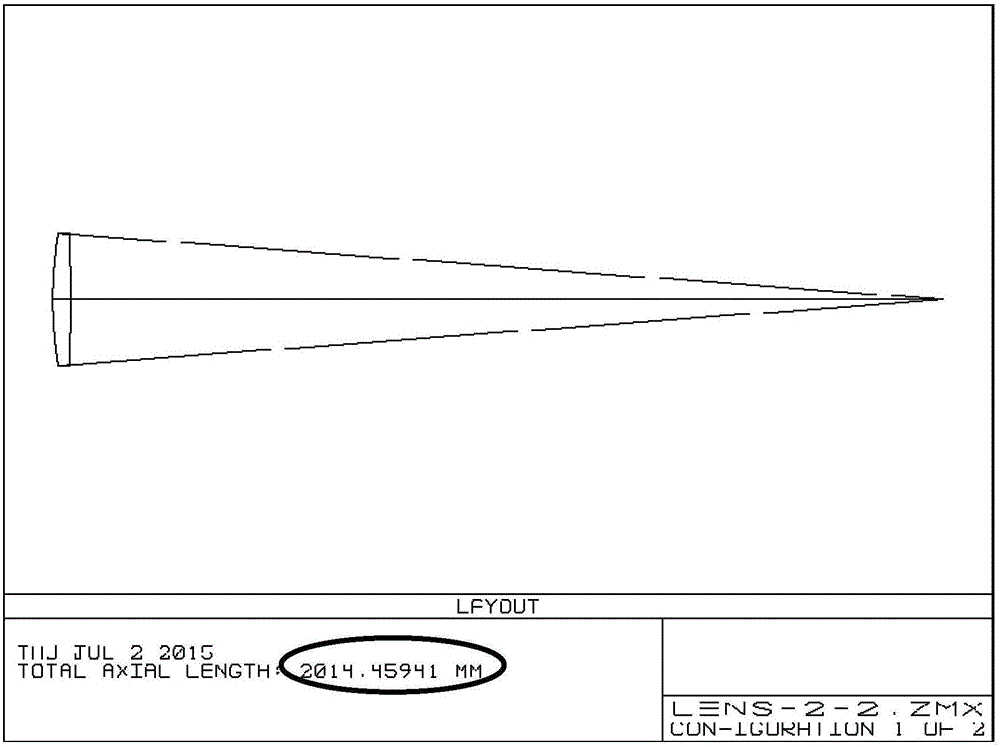
[0024] 1. ZEMAX software calculates the focal plane position or optical total length of the lens or optical system to be calibrated in the invisible light working band (see figure 1 , ellipse circle);

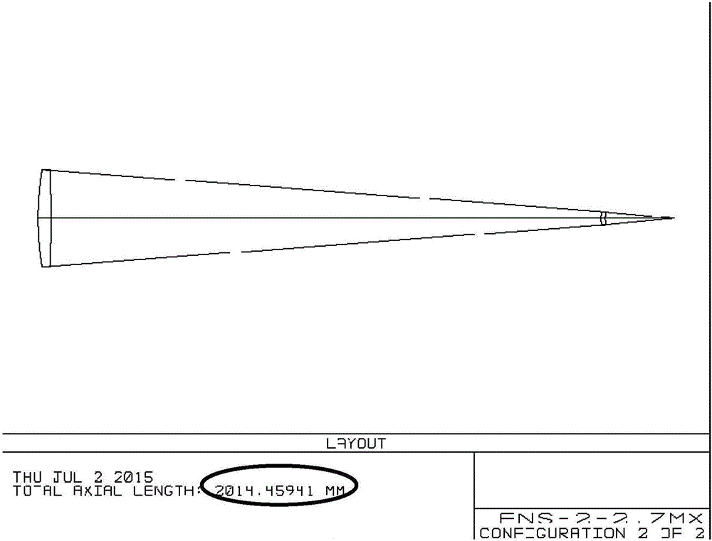
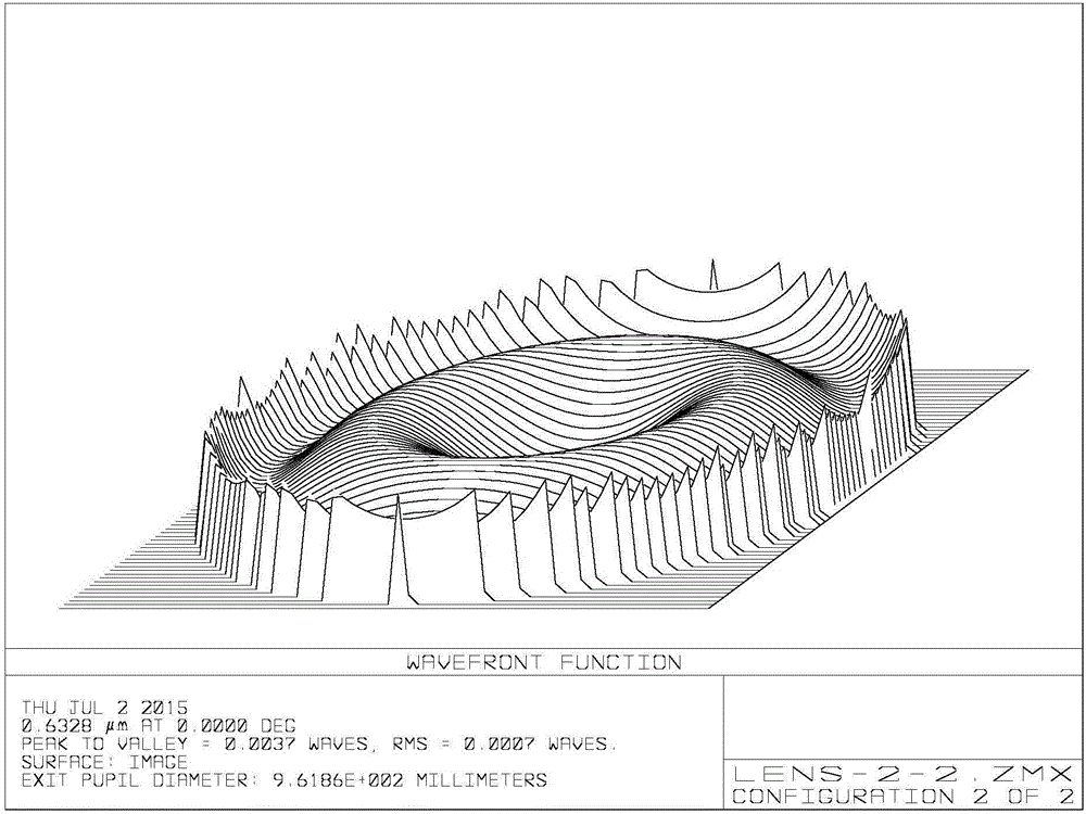
[0025] 2. Use the ZEMAX multi-structure module to design additional lenses, requiring the total optical length of the system or the additional back intercept "total optical thickness" to be equal to the back intercept of the lens or system to be calibrated, see figure 1 and figure 2 At the place marked with a red circle, it is also required that the image quality of the combined system should be better (the image quality requirement should not be lower than th...


PUM


Abstract

The invention discloses a method for calibrating the focal plane of an invisible light transmission optical system through a supplementary lens. The method specifically comprises the steps that 1, the position of the focal plane or the total optical length of a lens to be calibrated or the optical system to be calibrated at the invisible light wavelength band is calculated through ZEMAX software; 2, a ZEMAX multiple structure module is used for designing the supplementary lens, and the total optical length of the optical system or the supplementary back focal length total optical thickness is equal to the back focal length of the lens to be calibrated or the system to be calibrated; 3, the supplementary lens is machined, and optical parameters are measured; 4, an auto-collimation light path is established; 5, the focal plane is calibrated through the auto-collimation light path. The invention provides the method for directly determining the invisible light focal plane. The method is applicable to the design of a focal plane adjusting light path with a broad spectral range. The method has the advantages that the structure is simple, adaptability is high, cost is low, the adjustment method is reasonable and reliable, and operability is high.

Description

technical field [0001] The invention belongs to the field of optical detection, and in particular relates to a method for determining the focal plane position of an invisible light transmission optical system. Background technique [0002] Generally, simple invisible light transmission optical systems (such as near-ultraviolet and near-infrared bands) are not achromatized with visible light, such as aplanatic single lenses. When calibrating the focal plane position of the system, the invisible light band used is usually calculated based on the focus of visible light. For the lower focal plane position, the error of calibrated focal plane position is relatively large, and it is more difficult to meet the requirements of focal plane calibration for optical systems with smaller focal depth and higher image quality requirements. In the process of specific implementation, it is also necessary to ensure the concentricity and axial position of the focal plane assembly and the optic...

Claims


Application Information

Patent Timeline
Patent Type & Authority Applications(China)
IPC IPC(8): G01M11/02
Inventor 李季
Owner NANJING ZHONGKE ASTROMOMICAL INSTR
Why Eureka
Try Eureka