Ejection-compression refrigeration system with gas-liquid separator and utilization of low-grade heat energy

A gas-liquid separator, compression refrigeration technology, applied in refrigerators, refrigeration components, refrigeration and liquefaction, etc., can solve the problems of poor energy saving efficiency, low efficiency, high energy consumption, etc., to reduce energy consumption, high efficiency, reduce Effect of heat source temperature

Active Publication Date: 2017-10-13
冰山技术服务(大连)有限公司
View PDF7 Cites 0 Cited by
  • Summary
  • Abstract
  • Description
  • Claims
  • Application Information

AI Technical Summary

Problems solved by technology

[0004] In order to overcome the disadvantages of low efficiency, high energy consumption, inability to use lower temperature heat sources, and poor energy-saving efficiency of the existing injection-compression coupled refrigeration system, the present invention provides a high-efficiency, low-energy-consumption, A jet-compression refrigeration system with gas-liquid separator and low-grade heat energy that can use lower-temperature heat sources and has good energy-saving efficiency

Method used


Image

  • Ejection-compression refrigeration system with gas-liquid separator and utilization of low-grade heat energy

Examples


Embodiment Construction

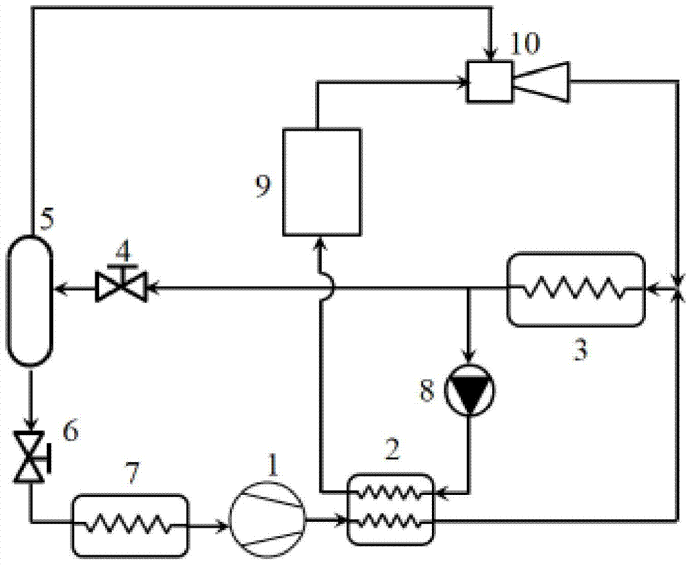
[0012] The present invention will be further described below in conjunction with the accompanying drawings.

[0013] refer to figure 1 , an injection-compression refrigeration system with a gas-liquid separator and utilizing low-grade heat energy, comprising a compressor 1, a preheater 2, a condenser 3, an evaporator 7 and an ejector 10, the outlet of the evaporator 7 is connected to The inlet of the compressor 1 is connected, the outlet of the compressor 1 is connected with the first inlet of the preheater 2, and the first outlet of the preheater 2 and the outlet of the ejector 10 are connected with the condenser 3 The outlet of the condenser 3 is divided into two routes, the outlet of the first route is connected with the second inlet of the preheater 2 through a pump 8, and the jet-compression refrigeration system also includes a first throttling device 4, a second Two throttling devices 6, a gas-liquid separator 5 and a generator 9 for converting liquid refrigerant into h...


PUM


Abstract

An ejection-compression refrigeration system with a gas-liquid separator and utilizing low-grade heat energy, the outlet of the evaporator is connected to the inlet of the compressor, the outlet of the compressor is connected to the first inlet of the preheater, and the first inlet of the preheater Both the outlet and the outlet of the ejector are connected to the inlet of the condenser. The outlet of the condenser is divided into two routes. The first outlet is connected to the second inlet of the preheater through the pump, and the second outlet of the condenser passes through the first section. The flow device is connected to the inlet of the gas-liquid separator, the gas-phase outlet of the gas-liquid separator is connected to the injection fluid inlet of the injector, and the liquid-phase outlet of the gas-liquid separator is connected to the inlet of the evaporator through the second throttling device. The second outlet of the heater is connected with the inlet of the generator, and the outlet of the generator is connected with the working fluid inlet of the injector. The invention has high efficiency, low energy consumption, can utilize a lower temperature heat source, and has good energy-saving efficiency.

Description

technical field [0001] The invention relates to the technical field of refrigeration, in particular to an injection-compression refrigeration system. Background technique [0002] With the continuous progress of human society, people's requirements for energy conservation and environmental protection continue to increase. Refrigeration technology consumes a large amount of energy every year and accounts for a large proportion of carbon emissions. Therefore, the development of energy-saving refrigeration technology is a hot topic today. [0003] The injection-compression coupled refrigeration system can improve system efficiency and reduce power consumption. The existing injection-compression coupling refrigeration cycle generally has two forms: first, use the ejector to recover the expansion work during the throttling process, use the high-pressure working medium to eject the low-pressure working medium, increase the suction pressure of the compressor, and finally increase...

Claims


Application Information

Patent Timeline
Patent Type & Authority Patents(China)
IPC IPC(8): F25B25/00F25B27/00F25B41/06F25B41/31
CPCF25B25/00F25B27/00F25B41/30
Inventor 徐英杰蒋宁
Owner 冰山技术服务(大连)有限公司
Why Eureka
Try Eureka