
Supporting rod fixing reinforcing device

A technology of strengthening device and arm rod, applied in the field of arm fixation strengthening device, can solve the problems of poor stability, difficult handling, insufficient strength, etc., and achieve the effects of increased mechanical strength, wide application range and simple structure

Inactive Publication Date: 2015-10-21
STATE GRID SHANDONG ELECTRIC POWER +1
View PDF4 Cites 0 Cited by
  • Summary
  • Abstract
  • Description
  • Claims
  • Application Information

AI Technical Summary

Problems solved by technology

[0002] The fixing of stop rods is widely used in areas with dense urban population and tight line corridors. Due to terrain restrictions, it is impossible to install guy wires. Some corner bars, T-connector bars, and terminal bars of 10kV distribution lines are mostly fixed by stop bars, especially in urban areas where line corridors are tense. Under the background, the installation method of the fixed rod is more common. At present, the fixed rod is mainly fixed with a semicircular hoop to fix the extension ring link method. This method has insufficient strength and poor stability. And the deflection of the tilting rod, it is very easy to cause the accident of falling rod
[0003] The main reason for this problem is that the extension ring fixing method is only for the horizontal force of the pole, and the closing pole can play a fixed role. However, during the construction process and daily operation, the closing pole is very susceptible to longitudinal and vertical forces, causing During the running process, there is a defect that the fixed end of the locking lever moves up and down and left and right
Once the up and down and left and right displacements of the fixed end of the lever occur, it will cause great hidden dangers to the safe and stable operation of the distribution line. The hidden dangers must be dealt with by power outages, which is difficult and takes a long time to deal with, causing great economic losses and social impacts on the power supply company.

Method used


Image

  • Supporting rod fixing reinforcing device
  • Supporting rod fixing reinforcing device
  • Supporting rod fixing reinforcing device

Examples


Embodiment

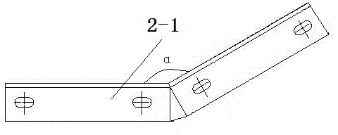
[0015] Embodiment: a kind of locking rod fixing strengthening device (referring to Figure 1-Figure 3 ), it includes a top iron 1 and a stop bar fixing frame 2. The top iron 1 is composed of an angle iron 1-1 and a U-shaped hoop 1-2 connected by bolts, and the clamping rod fixing frame 2 is composed of two "﹀" type fixing frames 2-1 and four string nails 2-2. Four string nails 2-2 are fixedly connected between the two "﹀" type fixing frames 2-1 by bolts, and the included angle α of the "﹀" type fixing frames 2-1 is 150°. Among them, the top iron 1 is made of a ?190mm U-shaped hoop and a ∠63*6*230mm angle iron, and is installed on the upper end of the fixed point between the stop bar 3 and the main body 4. The main function is to prevent the stop bar from moving up and down. The "﹀" type fixing frame 2-1 is made of ∠63*6*634mm angle iron, installed on the upper end of the fixing point of the stop bar 3 and the main body 4, and fixed with four ?18*320mm string nails 2-2. The ma...


PUM


Abstract

The invention discloses a supporting rod fixing reinforcing device. The supporting rod fixing reinforcing device is characterized by comprising ejecting iron (1) and a supporting rod fixing frame (2), the ejecting iron (1) is formed by connecting angle iron (1-1) and a U-shaped hoop (1-2) through a bolt, the supporting rod fixing frame (2) is formed by connecting two V-shaped fixing frame bodies (2-1) and four stringed nails (2-2), and the four stringed nails (2-2) are fixedly connected between the two V-shaped fixing frame bodies (2-1) through bolts. The supporting rod fixing reinforcing device is simple in structure, convenient to install, high in mechanical strength, good in stability and wide in application range.

Description

Technical field: [0001] The invention relates to a fixing and reinforcing device for a stop bar, which is widely used in the construction process of distribution lines in electric power systems and belongs to the technical field of distribution lines. Background technique: [0002] The fixing of stop rods is widely used in areas with dense urban population and tight line corridors. Due to terrain restrictions, it is impossible to install guy wires. Some corner bars, T-connector bars, and terminal bars of 10kV distribution lines are mostly fixed by stop bars, especially in urban areas where line corridors are tense. Under the background, the installation method of the fixed rod is more common. At present, the fixed rod is mainly fixed with a semicircular hoop to fix the extension ring link method. This method has insufficient strength and poor stability. And the deficiencies of the tilted rod are very prone to reverse rod accidents. [0003] The main reason for this problem ...

Claims


Application Information

Patent Timeline
IPC IPC(8): E04H12/20
Inventor 孙大为孔庆杰常宗学孙金玉洁胡林德都成业桑锐宫在武李书锋张晓明
Owner STATE GRID SHANDONG ELECTRIC POWER
Learn More