
Method for positioning optical center on the basis of concentric circle theory

A technology of concentric circles and positioning light, applied in the direction of television, electrical components, image communication, etc., can solve the problem of large optical center position error, and achieve the effect of ensuring quality

Active Publication Date: 2015-10-14
NINGBO SUNNY OPOTECH CO LTD
View PDF5 Cites 11 Cited by
  • Summary
  • Abstract
  • Description
  • Claims
  • Application Information

AI Technical Summary

Problems solved by technology

The traditional method is to analyze the brightness value of the entire image, and then take the average value to obtain the position of the optical center. It is required that there should be no target blocking objects during the test, and if the brightness distribution of the image within a certain range from the optical center position is uneven will lead to a large error in the calculated optical center position

Method used


Image

  • Method for positioning optical center on the basis of concentric circle theory
  • Method for positioning optical center on the basis of concentric circle theory
  • Method for positioning optical center on the basis of concentric circle theory

Examples


Embodiment Construction

[0028] The following description serves to disclose the present invention to enable those skilled in the art to carry out the present invention. The preferred embodiments described below are only examples, and those skilled in the art can devise other obvious variations. The basic principles of the present invention defined in the following description can be applied to other embodiments, variations, improvements, equivalents and other technical solutions without departing from the spirit and scope of the present invention.

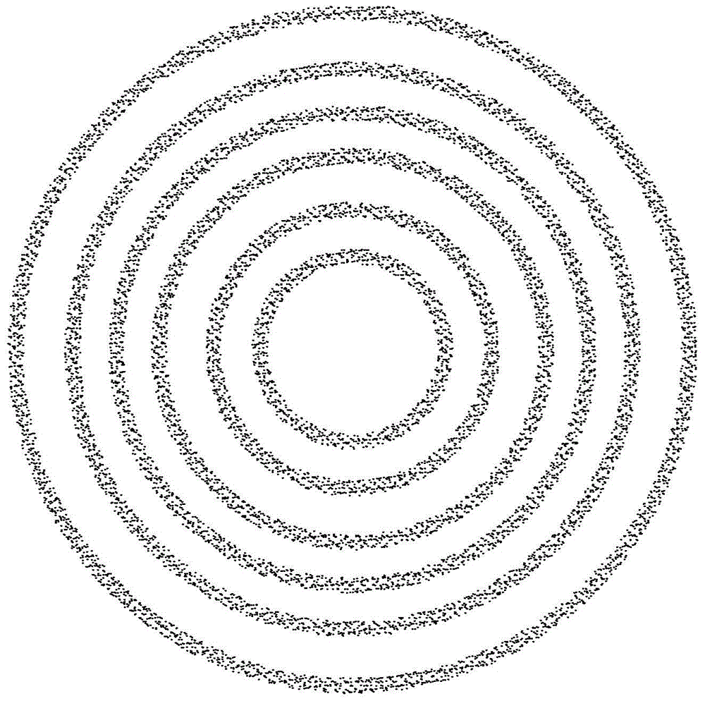
[0029] Such as figure 1 Shown in is the brightness distribution diagram of a standard image. It can be seen from the figure that the brightness in the image takes the optical center as the center and spreads around in the form of a circular wave. The farther away from the optical center, the higher the brightness value. Smaller, and the closer to the optical center, the greater the brightness value. Different distances from the optical center correspond...


PUM


Abstract

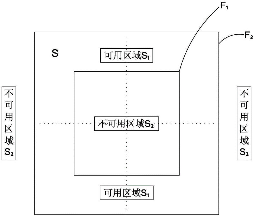
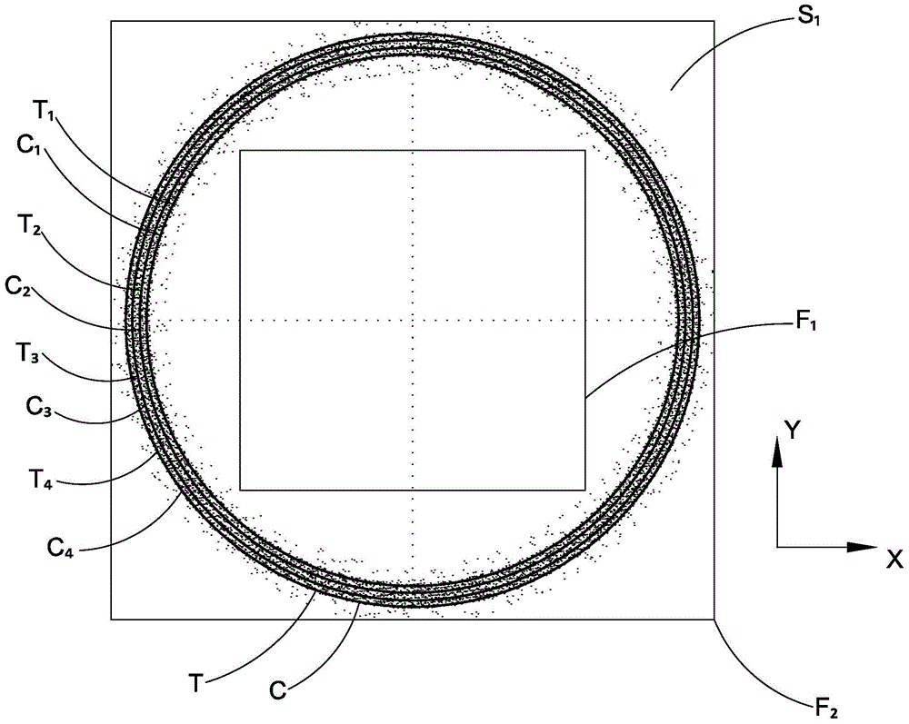
Provided is a method for positioning an optical center on the basis of a concentric circle theory. The method comprises the following steps of: (a) selecting at least one predetermined available area from a target image; (b) acquiring at least one group of brightness data approximately conforming to circle distribution in the available area according to at least one brightness gradient value; (3) performing circle fitting on the brightness data approximately conforming to circle distribution to obtain at least one concentric circle; and (4) computing the center of the concentric circles so as to obtain the position of the optical center. The method prevents brightness analysis of a whole target image in a conventional method, determines the position of the optical center by performing circle fitting on the extracted concentric circles. A calibration plate and other shielding objects are not required to be removed in a whole process and the optical center is effectively and fast positioned. Whether a product is subjected to a horizontal eccentricity is determined according to the position of the optical center such that the quality of the product is guaranteed.

Description

technical field [0001] The invention relates to a method for determining the optical center, in particular to a method for locating the optical center based on the theory of concentric circles. Background technique [0002] With the rapid development of the mobile phone industry, customers have higher and higher quality requirements for mobile phone camera modules. One of the important indicators is the horizontal eccentricity detection during module assembly. How to detect defective products caused by horizontal eccentricity Coming out will be the key to ensure product quality. The traditional method is to analyze the brightness value of the entire image, and then take the average value to obtain the position of the optical center. It is required that there should be no target blocking objects during the test, and if the brightness distribution of the image within a certain range from the optical center position is uneven It will lead to a large error in the calculated opt...

Claims


Application Information

Patent Timeline
Patent Type & Authority Applications(China)
IPC IPC(8): H04N17/00
Inventor 丁亮张宝忠张扣文廖海龙
Owner NINGBO SUNNY OPOTECH CO LTD
Learn More