
Display equipment and displaying control method thereof

A display control method and display device technology, which can be applied to picture duplicators, instruments, projection devices, etc., can solve the problems of low precision and slow focusing speed, and achieve the effect of precise autofocus and clear user experience

Inactive Publication Date: 2015-10-14
LENOVO (BEIJING) CO LTD
View PDF5 Cites 6 Cited by
  • Summary
  • Abstract
  • Description
  • Claims
  • Application Information

AI Technical Summary

Problems solved by technology

Usually, the user needs to manually focus the projection device according to the projected image he perceives, so the focusing speed is very slow and the accuracy is not high

Method used


Image

  • Display equipment and displaying control method thereof
  • Display equipment and displaying control method thereof
  • Display equipment and displaying control method thereof

Examples


Embodiment Construction

[0025] Hereinafter, preferred embodiments of the present invention will be described in detail with reference to the accompanying drawings.

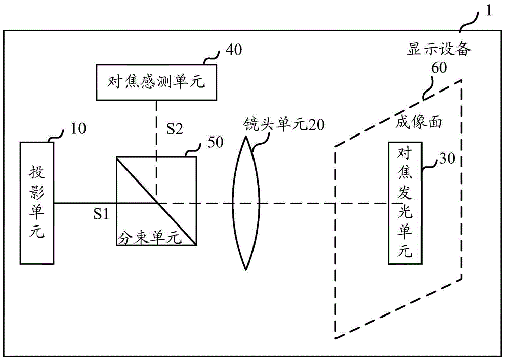
[0026] First, refer to figure 1 A display device according to an embodiment of the present invention is described. The display device 1 is preferably, for example, a digital light processor (DLP) using a digital micromirror (DMD) as a light valve imaging device. A DLP display device is composed of an analog-to-digital decoder, a memory chip, an image processor, and several digital signal processors (DSPs). All text and images are processed by analog-to-digital conversion to generate a digital signal. To the heart of DLP display devices - Digital Microreflective Devices (DMDs). After the light beam passes through the high-speed rotating three-color lens, it is projected on the DMD, and then projected on the large screen through the optical lens to complete the image projection. A piece of DMD, for example, is formed by many tiny square...


PUM


Abstract

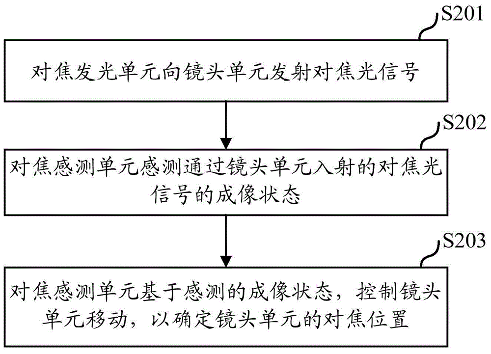
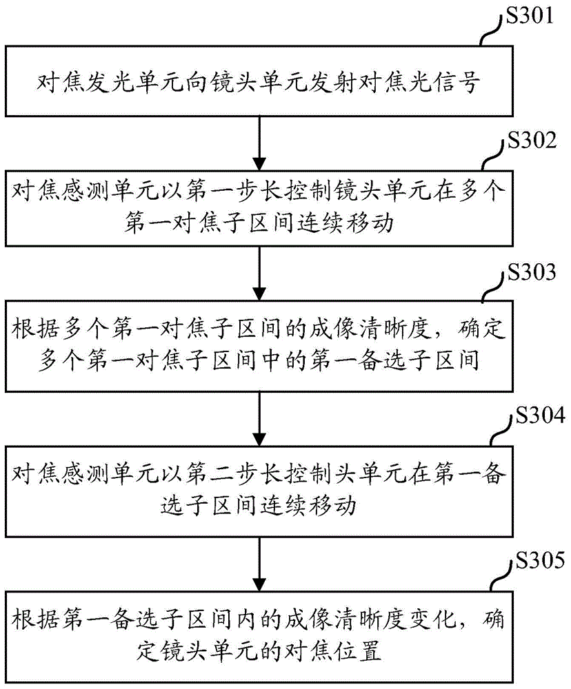
The invention provides display equipment which realizes automatic focusing and a displaying control method thereof. The display equipment comprises the components of a projection unit which is used for supplying an imaging optical signal to be displayed; a lens unit through which the imaging optical signal forms the to-be-displayed image on an imaging surface; a focusing and light-emitting unit which is configured on the imaging surface and is used for transmitting a focusing optical signal to the lens unit; and a focusing sensing unit which is used for sensing the focusing optical signal that enters through the lens unit and controlling movement of the lens unit according to the imaging state of the focusing optical signal, wherein an optical path between the projection unit and the lens unit is equal with that between the focusing sensing unit and the lens unit.

Description

technical field [0001] The present invention relates to the field of display devices, and more specifically, the present invention relates to a display device for realizing automatic focusing and a display control method thereof. Background technique [0002] With the development of technologies such as DLP (Digital Light Processing), projection equipment used to project images or videos onto a screen has become more and more compact and its cost has continued to decrease, making projection equipment widely used in homes, Offices, schools and entertainment venues, etc. [0003] Generally, when the usage state of the projection device changes, for example, when the distance between the projection device and the screen is changed, the projection device needs to be adjusted to obtain an optimal projection focusing effect. Usually, the user needs to manually focus the projection device according to the projected image perceived by the user, so the focusing speed is very slow an...

Claims


Application Information

Patent Timeline
IPC IPC(8): H04N9/31G03B21/53
Inventor 李翔
Owner LENOVO (BEIJING) CO LTD
Learn More