Electrical connector and method for manufacturing electrical connector

An electrical connector and adjacency technology, which is applied to the parts, connections, circuit/collector parts of the connecting device, etc., can solve problems such as complex methods

Active Publication Date: 2019-08-20
TE CONNECTIVITY GERMANY GMBH
View PDF5 Cites 0 Cited by
  • Summary
  • Abstract
  • Description
  • Claims
  • Application Information

AI Technical Summary

Problems solved by technology

These methods are relatively complex

Method used


Image

  • Electrical connector and method for manufacturing electrical connector
  • Electrical connector and method for manufacturing electrical connector
  • Electrical connector and method for manufacturing electrical connector

Examples


Embodiment Construction

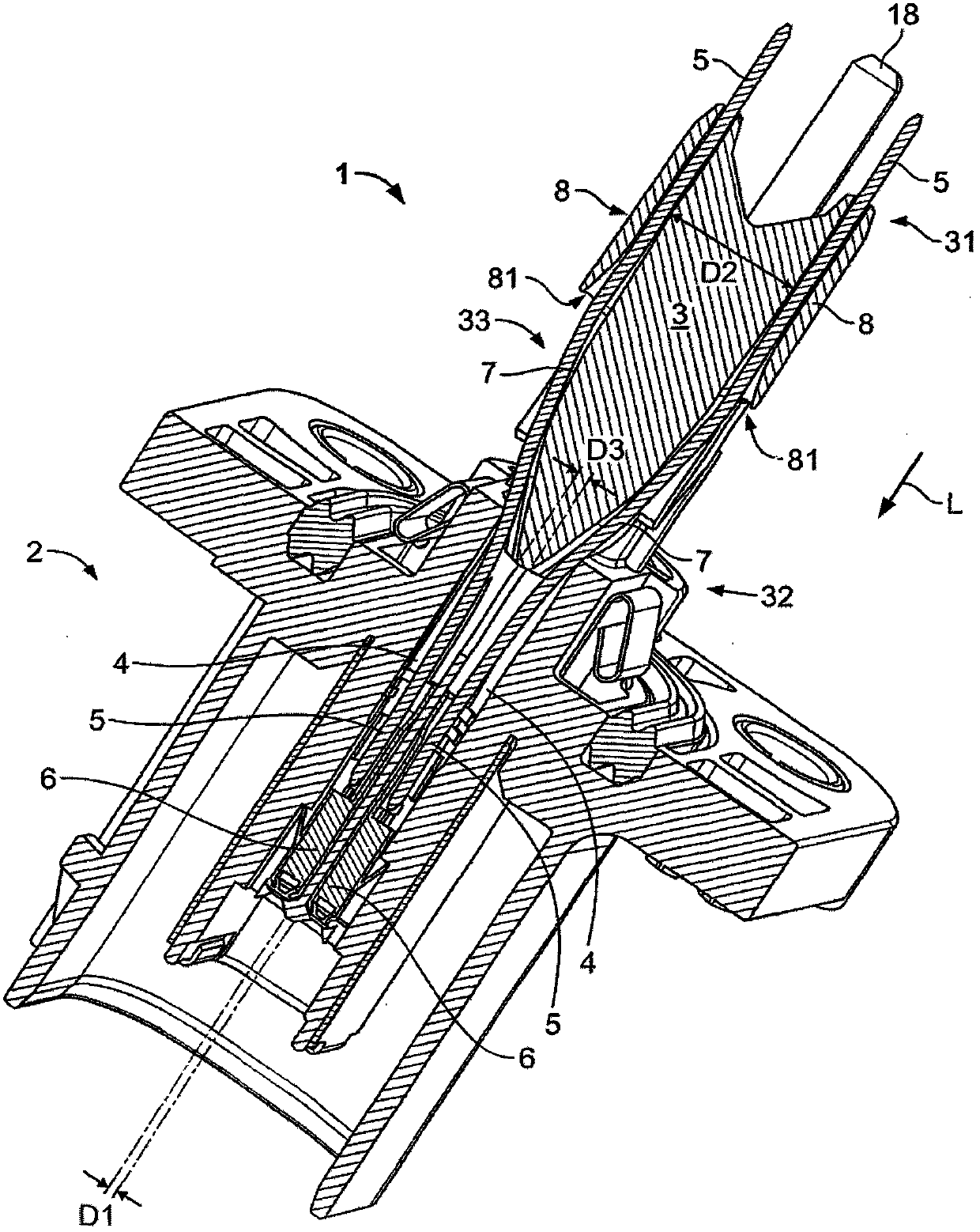
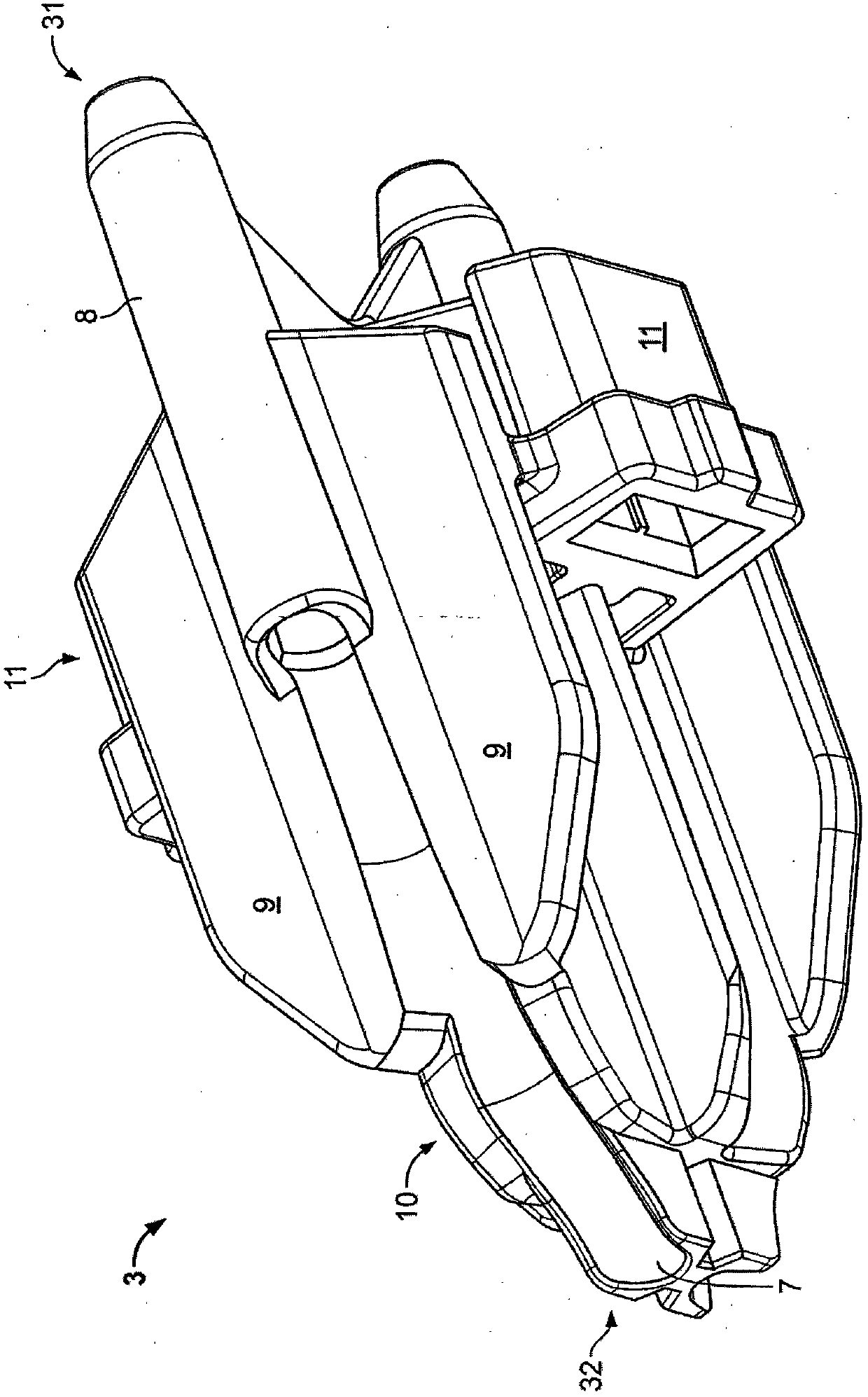
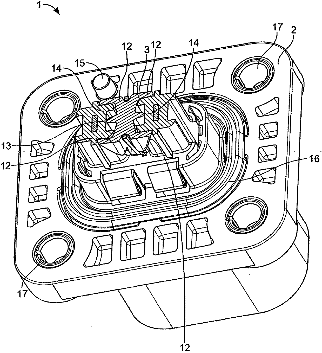
[0032] figure 1 An electrical connector 1 according to the invention is shown. It comprises a housing part 2 and an expansion part 3 .

[0033] In the housing part 2 there are two guide channels 4 for each contact element 5 . The contact elements 5 are designed as substantially rigid pins or pins and have a certain elasticity.

[0034] At the end of the contact element 5 arranged in the housing part 2, a terminal 6 in the form of a socket is mounted so that contact with a mating connector can be made in a simple manner. Alternatively, pin contacts can also be provided, for example. When it is not necessary to form a connection by plug-in, the contact element 5 can be fixed to the further conductor, for example by crimping or soldering.

[0035] The guide channels 4 extend in a linear manner and are parallel to each other in the longitudinal direction L through the housing part 2 .

[0036] The contact element 5 extends out of the housing part 2 and continues along the two...


PUM


Abstract

The invention relates to an electrical connector (1). The invention also relates to a method of manufacturing an electrical connector (1). Electrical connectors are used in various fields. It is often necessary to vary the spacing between two electrical conductors in the area of ​​the device. The object of the invention is to provide a simpler method than the prior art. This object is achieved by an electrical connector (1) having a housing part (2) with two guide channels (4) separated from each other and having two guide channels (4) each extending through the guide channel (4). An elongated contact element (5) with a flared part (3) having two flared faces (7) associated with the contact element (5) and facing away from the guide groove The ends (31) of the tracks (4) have a greater distance from each other than the guide channels (4), wherein the expansion part (3) tapers in the direction of the guide channels (4). In the inventive method of manufacturing an electrical connector (1), the opening member (3) is moved in the direction of the housing part (2) and the contact elements (5) are thus opened.

Description

technical field [0001] The invention relates to an electrical connector. The invention further relates to a method for manufacturing an electrical connector. Background technique [0002] Electrical connectors are used in various fields. It is often necessary to vary the spacing between two electrical conductors in the area of ​​the device. There are several ways to achieve this goal. In the first method, flexible conductors such as cables are used. The disadvantage of this situation is that, in order to contact the flexible conductor, other components need to be mounted to the conductor, for example when the conductor is intended to be soldered to a board. In another prior art method, a rigid conductor is bent into the proper form and then inserted. In a third method, the rigid conductors are manufactured to form, eg stamped from sheet metal into the correct form. These methods are relatively complex. Contents of the invention [0003] The object of the invention i...

Claims


Application Information

Patent Timeline
Patent Type & Authority Patents(China)
IPC IPC(8): H01R13/516H01R13/40H01R43/20
CPCH01R13/4367H01R13/533H01R43/20Y10T29/49204H01R13/502H01R43/00H01R43/22
Inventor M·利斯廷S·西格特
Owner TE CONNECTIVITY GERMANY GMBH
Why Eureka
Try Eureka